Larry: What are you trying to do? You have 1.4V on the input and 1.2V at the Xformer primary. It seems to me that all you need is a buffer for current gain. E
In the last drawing, the output transformer has 0vDC and 0vAC on the primary. Also it looks like the two first gain stages are supposed to handle one phase of the signal each, but the feedback resistor values are different, Ill bet that is not what you wanted. 🙄 Uh keep trying.
Also it looks like the two first gain stages are supposed to handle one phase of the signal each, but the feedback resistor values are different, Ill bet that is not what you wanted.
The feedback resistors need to be different. The gain of an inverting amp is Rf/Ri, the gain of a non-inverting amp is Rf/Ri + 1.
Ah Glenb - I learned something 🙂 Larryb - what is your thinking here? What is the over all design goal?
This is for an oscillator , not for audio in particular .
Im confused , what is wrong with this design .
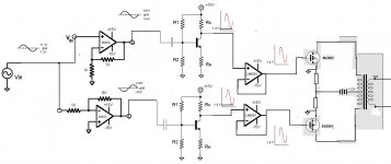
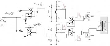
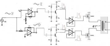
The first 2 gains stages with the lm833 should be the same amplitude , but inverted , sorry if it is not .
Can anybody tell me whats wrong with the design , what could be made better , thx . I am trying to replace the transformer from the zeus design , this seems like it replaces a transfo witgh the battery in the middle to me when i just think at the waveform .
Im confused , what is wrong with this design .
The first 2 gains stages with the lm833 should be the same amplitude , but inverted , sorry if it is not .
Can anybody tell me whats wrong with the design , what could be made better , thx . I am trying to replace the transformer from the zeus design , this seems like it replaces a transfo witgh the battery in the middle to me when i just think at the waveform .
Firechief I see yopu are confused by the image .
The 1,4 V is just my bias , I wish this to go up to about 15 volts , to get the maximum output out of the battery and to barely bias the mosfets so they stay in continuous conduction .The vgs of a mosfets like this is about 1.5 volts or lower .
The 1,4 V is just my bias , I wish this to go up to about 15 volts , to get the maximum output out of the battery and to barely bias the mosfets so they stay in continuous conduction .The vgs of a mosfets like this is about 1.5 volts or lower .
My goal is to have an pure sine oscillator for the 300-25000 hz range , pure sine voltage and current with no commutation glitches 100% linear , good with reactive loads .
To step up and isolate voltage @ about 50 volts with a load of about 35 ohms or higher , of capacitive , inductive or resistive phase angle .
Firechief I believe you are extremely confused , plz explain what you are trying to communicate .
To step up and isolate voltage @ about 50 volts with a load of about 35 ohms or higher , of capacitive , inductive or resistive phase angle .
Firechief I believe you are extremely confused , plz explain what you are trying to communicate .
Last edited:
you have the FET sources grounded and connected to the transformer which also has a grounded center tap.....
So, is this thing supposed to oszillate by itself, or is it supposed to amplify a given sinewave signal? (I guess the latter)
You want 50V amplitude, and a galvanic isolated (floating) output (thus the xformer).
You could use a tuneable sinewave oscillator for the desired frequency range followed by a conventional amp (without outputsignal xformer) providing the desired voltage and power, both with floating supplies (no connection to earth) and you're done. And would be a lot purer than your no feedback approach with the fets, as it is so far.
If your oscillator won't provide a floating supply/signaloutput, you could use a signal xformer at the input of the floating amp.
Having all those active components, surely it will not be pure, would a single element oscillator such as Colpits, Hartley or Wein bridge not suffice?
The ground sign is the gnd of my wall +-15 volts power supply . I have a spure sine ac signal ref to ground .
Why no feedback ? I have unity gain and feedback @ the gate .
The Ov is the battery . Is this wrong ? should both my battery and power supply ground be the same , I tought the amplifier line was meant to be as short as possible .
I do not understand the concept of floating output or grounded output , what is this all for . Whats bad about having a floating ouput , I seen this everywhere .
I am looking for some more info .
Last edited:
unclejed 631 has explained it well "you have the FET sources grounded and connected to the transformer which also has a grounded center tap....."
Trace the output circut from the batt supply through the transformer to what is drawn as ground. Look at it from a DC perspective and you will see that both ends of the tranformer are grounded.
Trace the output circut from the batt supply through the transformer to what is drawn as ground. Look at it from a DC perspective and you will see that both ends of the tranformer are grounded.
what do you want to do, that you explicitly need a floating output.
By floating I mean, none of both generator/source terminals are connected to a reference potential within the generating device (e.g. the secondary winding of a xformer is a floating output), so it can be connected to an external reference potential (that of the DUT).
In case the output was not flaoting this would only be possible if both reference potentials can be connected together (e.g. because they are the same) without compromising the system (e.g. creating a short).
If you want a floating output, via the transformer, why not drive the primary single ended with a simple class A?
larryB: We still do not know what you wold like to accomplish.
To answer one Q: a floating output can allways be grounded, but you can not float a grounded (single ended) output (oh, my head hurts!). Think of it as a balanced (floating) line and an unbalanced (grounded) line.
To answer one Q: a floating output can allways be grounded, but you can not float a grounded (single ended) output (oh, my head hurts!). Think of it as a balanced (floating) line and an unbalanced (grounded) line.
you could drive a single ended transformer with an LM3886, and get the same results with less complication, and a simpler transformer.
So I believe I understand what you mean , both must be common grounded like this ,I tought vgs meant the source of mosfet was gonna be whatever voltage at gate -Vgs , I guess thats when both have same common ground . Trying to get a electronics phase splitter zeus type .
But then I have no longer a pure capacitive load on the op amp driver , but an RLC load , so now that could be trouble .
I use push pull for the following reasons , I believe it will be less work to design a single good center tapped than a big bulky single ended transfo , the transfo is the most costly and annoying remember .
What Do the Terms Push-Pull and Single-Ended Mean?
But then I have no longer a pure capacitive load on the op amp driver , but an RLC load
, so now that could be trouble .I use push pull for the following reasons , I believe it will be less work to design a single good center tapped than a big bulky single ended transfo , the transfo is the most costly and annoying remember .
What Do the Terms Push-Pull and Single-Ended Mean?
Attachments
Last edited:
- Status
- Not open for further replies.
- Home
- Amplifiers
- Solid State
- Can this work ?