I have a box full of 6n6p and 6c33c-b tubes. I saw a OTL design with 6c33c-b tubes but with a other driverstage. A nice driverstage i saw by triodedick. The ecc99 is almost compatible with the 6n6p tube. So i combined both schematics.
Who can tell me if this will work?
Orginal driver.
Orginal OTL .
New combination
Who can tell me if this will work?
Orginal driver.
An externally hosted image should be here but it was not working when we last tested it.
Orginal OTL .
New combination
An externally hosted image should be here but it was not working when we last tested it.
I do not think you will get the desired result with your Circuit modifications.
If you look at the Original OTL circuit, Look at B, the connection Between the output and the driver. Labeled negative feedback.
You omitted it completely in your drawing.
This is what lowers the output impedance from the 200 ohms a pair of 6C33 would produce as Cathode followers to the 2 ohms or less required to drive a speaker. Also, the 6C33 isn't the most linear beast in the world. MonoBill can probably sound good without Feedback because the output tubes are presented with a load that is appropriate to them.
If I liked the original OTL schematic, I would simply get a couple of 12AU7 or 6SN7 tubes per channel and build it. I would not use this circuit to drive anything more expensive than an NSB, ($0.69)because the entire bias current is run through the speaker coil.
I am not an expert on OTL, but this does not look like a happy design choice IMHO. YMMV. ETC.
Next up in the complexity scale would be to replace the 12AU7 in the schematic and re-compute all of the resistor values. Since I graduated from school before Spice was taught, Multiple feedback loops give me headaches. The nice thing is the 6H6 have about the same gain as a 12AU7, so the ratios of the resistors would be unchanged.
I would also read the entire Tube Cad Journal website, Buy the Designing Valve Amplifiers and ask a bunch more questions before you melt any solder in an OTL design of your own.
Good luck with your quest.
Regards;
Doug
It'll "work" after a fashion, as in it'll probably make noise, but that's about it. The one labeled "Original OTL" is a topology called an "inverted Futterman". The one you propose is just a very basic SEPP. The A Number One problem with the SEPP is that the triode on the bottom has its cathode firmly nailed to AC ground, but the cathode of the top triode floats with the output. That means a nasty imbalance as the bottom triode has a higher voltage gain. The inverted Futterman takes care of that by means of local feedback, so that both sections have nearly the same voltage gain.
The only way to use an LTP splitter is by adding cathode follower drivers which are wired to provide the necessary local NFB to restore inverted Futterman operation.
I, personally, would avoid that particular topology completely. If I was going to do a VT OTL (and I might someday) I'd go with the Inverted Topology. (See: Steve Bench's Site for more articles on this.) This gives naturally low voltage, high current operation, and makes for easy DC offset compensation. The A Number One drawback is the need to swing some big volts at the input, and that'll take a power supply for the front end of at least 500Vdc for decent linearity in the driver. Not easy, but not insurmountable either.
Hi,
The 6C33C has an output impedance as cathode follower of ~27ohm not 200! furthermore if using the inverted Futterman circuit the output impedance will be as for 2 cathode followers in parallel meaning about 13 ohm, this impedance can then be further reduced by quite moderate feedback. If 6C33C is a linear tube or not maybe depends on what you compare with but many are happy with this tube in SE amps and OTLs with and without feedback.
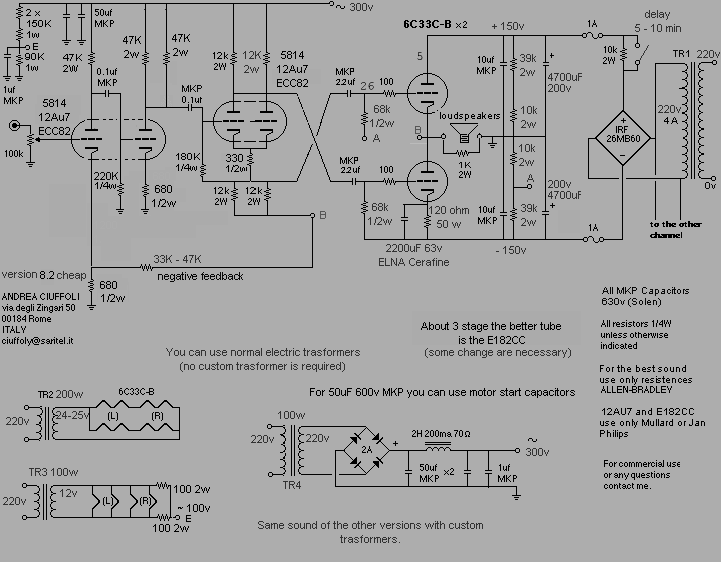
To the original poster I would recommend to use the Ciuffoli circuit or something similar as this http://www.tubetvr.com/otl.html and either use the input tubes as designed or redesign it for what you have.
BTW the bias current doesn't go through the speaker as there is no DC voltage over it, the circuit is safe to use with any speaker.
Regards Hans
The 6C33C has an output impedance as cathode follower of ~27ohm not 200! furthermore if using the inverted Futterman circuit the output impedance will be as for 2 cathode followers in parallel meaning about 13 ohm, this impedance can then be further reduced by quite moderate feedback. If 6C33C is a linear tube or not maybe depends on what you compare with but many are happy with this tube in SE amps and OTLs with and without feedback.
To the original poster I would recommend to use the Ciuffoli circuit or something similar as this http://www.tubetvr.com/otl.html and either use the input tubes as designed or redesign it for what you have.
BTW the bias current doesn't go through the speaker as there is no DC voltage over it, the circuit is safe to use with any speaker.
Regards Hans
Thanks all for the fast reply.
I understand now that negative feedback is important for the inverted futterman circuit. I know there are enough other schematics whop are proven to work. But i like the one tube driver/phase splitter.
Can i make a one tube driver/ fasesplitter with the feedback i needed?
I understand now that negative feedback is important for the inverted futterman circuit. I know there are enough other schematics whop are proven to work. But i like the one tube driver/phase splitter.
Can i make a one tube driver/ fasesplitter with the feedback i needed?
Can i make a one tube driver/ fasesplitter with the feedback i needed?
Yes in theory you can if you use an ordinary LTP and connect it directly to the output tubes as indicated here http://www.tubecad.com/articles_2001/totem-pole_output_stage_psrr/page8.html
However it will not work very well as the total gain is 0 so you need an input stage with quite a lot of gain so you can apply feedback in order to lower the output impedance to a reasonable value.
Why do you want to use just one input tube? Isn't it better to build a already proven design that work?
I am fond of the split load phase inverter as it perfectly balanced, you just need 2 equal resistors for the anode and cathode. The disadvantage of the split load is that it requires quite a lot of anode voltage if you need high output voltage, I use 450V in my own OTL but that is enough to get a low distortion drive for the output tubes.
Regards Hans
I have redesign the schematic. But now i need 2 tubes. One for gain and one as phasesplitter.
I still like to use one tube.
An externally hosted image should be here but it was not working when we last tested it.
I still like to use one tube.
In the last schematic was not quite right. Here a update.
Design goals:
- Cancelling powerrail noise/hum
- Correct gain differrence between upper/lower outputstage
- Fixed bias between 200 and 250mA
- Simple power supply
- Use 6n6 and 6c33 tubes
- 20 Watt output at 8 ohm
The input SRPP stage has a 11 x gain this looks to low. But my input signal is 4 V.
An externally hosted image should be here but it was not working when we last tested it.
Design goals:
- Cancelling powerrail noise/hum
- Correct gain differrence between upper/lower outputstage
- Fixed bias between 200 and 250mA
- Simple power supply
- Use 6n6 and 6c33 tubes
- 20 Watt output at 8 ohm
The input SRPP stage has a 11 x gain this looks to low. But my input signal is 4 V.
tubetvr said:
However it will not work very well as the total gain is 0 so you need an input stage with quite a lot of gain so you can apply feedback in order to lower the output impedance to a reasonable value.
Why do you want to use just one input tube? Isn't it better to build a already proven design that work?
I am fond of the split load phase inverter as it perfectly balanced, you just need 2 equal resistors for the anode and cathode. The disadvantage of the split load is that it requires quite a lot of anode voltage if you need high output voltage, I use 450V in my own OTL but that is enough to get a low distortion drive for the output tubes.
Regards Hans
Dear Hans,
All the other designs do not use 6N6P and 6C33c-B tubes, i got a lot of them and i like the sound of the 6N6 tube.
Futher the powersupply must be cheap, this means use cheap transformators such as 230Vprim/2 x 115Vsec for powerstage, 230Vprim/2 x 12V for filaments and 230Vprim/230Vsec small one for input and driverstage.
6n6p and 6c33c OTL
Hi:
I like to know if you test this circuit and if you make some modification. The 6n6 are high quality tube and wish make his design…
Please let me know...
Happy new year.
Alberto.
Hi:
I like to know if you test this circuit and if you make some modification. The 6n6 are high quality tube and wish make his design…
Please let me know...
Happy new year.
Alberto.
I agree!!!Hi:
I like to know if you test this circuit and if you make some modification. The 6n6 are high quality tube and wish make his design…
Please let me know...
Happy new year.
Alberto.
Koifarm please keep this one going. I think there may be others interested to build this.
Member
Joined 2002

You might want to look at this thread:
http://www.diyaudio.com/forums/tubes-valves/161112-what-tubes-tube-amp-18.html
It will allow you to use feedback at your discretion. It will run fine with 6C33s but the bias voltage will be a little different.
http://www.diyaudio.com/forums/tubes-valves/161112-what-tubes-tube-amp-18.html
It will allow you to use feedback at your discretion. It will run fine with 6C33s but the bias voltage will be a little different.
- Status
- Not open for further replies.
- Home
- Amplifiers
- Tubes / Valves
- Can this schematic work? 6N6P driver with 6C33C-B OTL