Hi All
I think here are also russian guys.
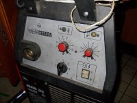
I have a question not related to audio but a power converter for welding.
It is cyrillic and I like if someone can translate it in english for me, or dutch.
I can not see for shure what to do with transformer winding etc, and it is high power so need a good translation, so my russian friend I thank you already.
regards
kees
I think here are also russian guys.
I have a question not related to audio but a power converter for welding.
It is cyrillic and I like if someone can translate it in english for me, or dutch.
I can not see for shure what to do with transformer winding etc, and it is high power so need a good translation, so my russian friend I thank you already.
regards
kees
Attachments
Would scanning the picture and using OCR software (optical character recognition) work.
You could then get the text off the circuit as a text file and copy and paste into google translate. No idea if it would work or not but worth a play maybe.
You could then get the text off the circuit as a text file and copy and paste into google translate. No idea if it would work or not but worth a play maybe.
Mooly's suggestion is excellent (why doesn't it surprise me?)😉
I snipped text parts out of the schematic, such as what's attached,
then
OCR'd it at
Free online OCR
and pasted Cyrillic text in Google translate, result was:
welding apparatus
Current 5 - 165 A
Electrodes up to 4 mm
2005
Do it part by part.
Don't waste time on single letters, you already know (or should) the "B" is "V" , "P" is "R" and so on.
That said, what are you trying to do?
If repairing such machine, the schematic will do; if trying to clone one, forget it.
The transformers shown are custom wound and there is no data on the schematic about them, not even voltages, current or anything else.
The machine is basically an SMPS, where you can get from (estimated) 15 to 60V or thereabouts and current (rated) from 5 to 160A.
I know, I weld myself.
In fact, they state it's enough for 4mm electrodes; personally with 160A I would be happy with up to 2.5mm ones; 3 mm as a limit.
4 mm ones will drive you crazy, sticking every few minutes because they will not become hot enough.
You *can* weld with them, but you'll need a surgeon's firm hand.
That said, the big problem will be Tr3 , the output one, and the choke Dr1.
Anyway, good luck 🙂
Attachments

Mooly's suggestion is excellent (why doesn't it surprise me?)😉
I snipped text parts out of the schematic, such as what's attached,
then
OCR'd it at
Free online OCR
and pasted Cyrillic text in Google translate, result was:
welding apparatus
Current 5 - 165 A
Electrodes up to 4 mm
2005
Do it part by part.
Don't waste time on single letters, you already know (or should) the "B" is "V" , "P" is "R" and so on.
That said, what are you trying to do?
If repairing such machine, the schematic will do; if trying to clone one, forget it.
The transformers shown are custom wound and there is no data on the schematic about them, not even voltages, current or anything else.
The machine is basically an SMPS, where you can get from (estimated) 15 to 60V or thereabouts and current (rated) from 5 to 160A.
I know, I weld myself.
In fact, they state it's enough for 4mm electrodes; personally with 160A I would be happy with up to 2.5mm ones; 3 mm as a limit.
4 mm ones will drive you crazy, sticking every few minutes because they will not become hot enough.
You *can* weld with them, but you'll need a surgeon's firm hand.
That said, the big problem will be Tr3 , the output one, and the choke Dr1.
Anyway, good luck 🙂
Wel like I say it is already translated, the trafo can be made myself easely.
I do not use electrodes I do use welding wire in a Co2 welder who has a died trafo, I do use this
inverter for that instead, I go build this pcb into the Co2 welder housing, I have not a repair, I can read schematics, not a problem.
I now SMPS I repear a lot of that supplys even the computer ones, I go make a pcb for this.
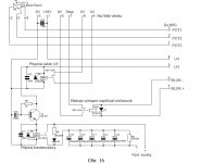
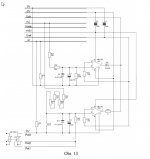
1. Title (in the middle): Welding machine ; Current 5-165A ; electrode up to 4mm ; 2005
2. various text in the schematic: (middle left): "регулировка тока" - current regulator ;
(middle right , (+) and (-) ): "к электродам" - to electrodes ;
(bottom left): "датчики на замыкание при 90 гр." - short circuit sensor at 90 degr. ; (green LED): "работа" - operating ; (red LED): "останов по перегреву" - stop due to excessive heat ; (yellow LED): "нагрев" - heating ;
text near transistors KT814 and KT805: temperature sensor for automatic fan speed control.
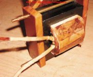
The remaining Text at bottom right is description of the transformers.
"витков" - number of windings (for each coil) ; "ПЭВ" is the name of the wire used (actually this is a standard copper wire for transformers), followed by its thickness in mm. ; "Зазор" - gap (air gap).
Transformer number 3 is a bit different than the other - 1st coil (primary, I ) is 18 windings of 5x1.2mm flat wire ; 2nd coil (secondary, II) is 6 windings of 65x0.5mm flat wire, as far as I understand they recommend winding it on top of the primary one, on the whole width of the bobbin.
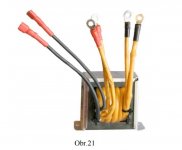
"Др1" - steel, gap 5mm, 18 windings of flat copper wire 0.6x40mm, ~70-90uH
The steel is from the type shown here: Ìàãíèòîïðîâîäû ØË | Áðîíåâûå | Ìàãíèòîïðîâîäû | "ÒîðÒðàíñ" - ïðîèçâîäñòâî òðàíñôîðìàòîðîâ, àâòîòðàíñôîðìàòîðîâ, äðîññåëåé, ïðåîáðàçîâàòåëåé íàïðÿæåíèÿ, êóïèòü òðàíñôîðìàòîð, ñåðäå÷íèêè.
"Тт" is a toroid (actually two) size 20x10x5mm , 100 windings 0.2mm
Other symbols: "в"=V ; "вт"=W (watt) ; "мк"="мкф"=uF
I hope my translation will be of some help to you.
regards
Attachments
Last edited:
Glad you solved it 🙂 😀 😛
Congratulations.
It will be ready for working, only the wire on the ferrite E55 core has to be 90 x 0.2 mm and 65 x 0.2 mm litze wire who i have to make myself.
Attachments
You will probably know this site. But still
BLOCK Transformatoren-Elektronik GmbH :::: Produkte
Thanks
yes i dit now but for 150 ampere I need big litze in total this go to max 3.5 amp.
made this myself is not so difficult I think just a lot of work.
Is is quite a while back, but I am busy with make one, winding the trafo is after some practicing not so difficult at all, only some work making litze but for the welding output I use flat copper and noth thicker then 2 x scin effect, here I am bound to a max frequentie but 25/35 Khz is fine for this kind of stuff. original in this schematic is 60 Khz but maybe I go just like schematic advise.
I go use it for MIG/MAG and therefore need a voltage feedback pot, I have found a nice schematic who can do mig/mag stick and TIG in one machine.
But I think only mig mag is needed, so I can remove some circuits make it simple.
The biggest challence with high power inverters is the pcb layout, it is very important to drive the full bridge well with good drivers, and short paths in pcb layout, if one igbt oscillates just for a moment things blow up..
IT is also nice test for amplifier supplys.
regards
Attachments
-
 ScreenHunter_512 Apr. 14 14.55.jpg66.9 KB · Views: 53
 -
 ScreenHunter_511 Apr. 14 14.55.jpg45 KB · Views: 49
 -
 ScreenHunter_510 Apr. 14 14.54.jpg80.2 KB · Views: 55
 -
 ScreenHunter_509 Apr. 14 14.54.jpg91.5 KB · Views: 57
 -
 ScreenHunter_508 Apr. 14 14.53.jpg104.4 KB · Views: 62
 -
 ScreenHunter_513 Apr. 14 14.56.jpg29.7 KB · Views: 49
Last edited:
- Status
- Not open for further replies.
- Home
- Member Areas
- The Lounge
- Can someone translate this cyrillic