I don't know if it's correct ... but it does appear to make sense. Pretty standard design, actually.

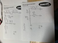
The topology seems to make sense. The woofer uses a fourth order electrical and the tweeter uses third order electrical.
The caps appear to be electrolytic so it makes sense to replace them with better quality caps.
As for the 1.4Ohm resistor, are you sure it belongs to the woofer? I would double check to make sure it's not being use on the tweeter xover.
The caps appear to be electrolytic so it makes sense to replace them with better quality caps.
As for the 1.4Ohm resistor, are you sure it belongs to the woofer? I would double check to make sure it's not being use on the tweeter xover.
Andy2
I double checked and it sure is on the woofer circuit. Part of why I’m asking as I haven’t seen topology like this on woofers before. *but* it seems like I do more reading than building.
- Jeff
I double checked and it sure is on the woofer circuit. Part of why I’m asking as I haven’t seen topology like this on woofers before. *but* it seems like I do more reading than building.
- Jeff
Part of why I’m asking as I haven’t seen topology like this on woofers before.
- Jeff
Yeah, usually the 33uf is omitted on the woofer, but I guess Paradigm uses asymmetric xover to align the driver phase - fourth order for the woofer and third order.
Most diy does somewhat opposite - that is third order for the woofer and fourth order for the tweeter.
- Home
- Loudspeakers
- Multi-Way
- Can someone smarter then me check my crossover tracing