I have found this module in my junk box, and wonder if anyone can identify it.
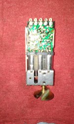
It looks like a permeability slug tuned FM tuner to me. It is marked Sanshin Japan, as manufacturer, and has a label with two part numbers: 1512Y is printed, and 151840 is handwritten.
The source is almost certainly a mid 1970's Radio Shack surprise box, as I would pick a few up whenever they became available when I was employed there. Obsolete spare parts were among the many things that got swept into these boxes.
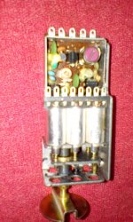
It is a really nice piece, with six slug tuned inductors on a threaded jackscrew, three of which are in use and soldered to the pcb.
I'm trying to figure out the connections to the pins. Starting at the pink IF XFMR, it appears the
first pin is an unbalanced antenna input;
second pin is ground;
third pin is IF output;
fourth pin is B+, and
fifth is unknown
I am wondering if the fifth pin is an oscillator input.
There are three bipolar transistors. One would have to be an RF amplifier. One would have to be a mixer. The third I thought might be the oscillator, but it could also be a second RF stage, tuned by the third slug.
The shield is labeled IFT above the transformer. The small trimmer cap is labeled OT ( Oscillator tune ?). The other two are TP. It appears the only actual test point is above the IFT, near the trimmer.
Just wondering if someone ran across one of these before, and might have some knowledge of it's characteristics.
Win W5JAG
It looks like a permeability slug tuned FM tuner to me. It is marked Sanshin Japan, as manufacturer, and has a label with two part numbers: 1512Y is printed, and 151840 is handwritten.
The source is almost certainly a mid 1970's Radio Shack surprise box, as I would pick a few up whenever they became available when I was employed there. Obsolete spare parts were among the many things that got swept into these boxes.
It is a really nice piece, with six slug tuned inductors on a threaded jackscrew, three of which are in use and soldered to the pcb.
I'm trying to figure out the connections to the pins. Starting at the pink IF XFMR, it appears the
first pin is an unbalanced antenna input;
second pin is ground;
third pin is IF output;
fourth pin is B+, and
fifth is unknown
I am wondering if the fifth pin is an oscillator input.
There are three bipolar transistors. One would have to be an RF amplifier. One would have to be a mixer. The third I thought might be the oscillator, but it could also be a second RF stage, tuned by the third slug.
The shield is labeled IFT above the transformer. The small trimmer cap is labeled OT ( Oscillator tune ?). The other two are TP. It appears the only actual test point is above the IFT, near the trimmer.
Just wondering if someone ran across one of these before, and might have some knowledge of it's characteristics.
Win W5JAG
Attachments

Last edited:
Maybe the fifth lug is the AFC input. Is there a varicap in parallel with the oscillator's resonant circuit?
Best regards!
Best regards!
Thanks, guys!
@ gmphadte - Actually, no, it had not occurred to me that this would be a replacement part for an old car stereo, but it makes sense. Looks to be a single RF stage, it takes about four turns to go from the slugs fully extended to fully bottomed, so not really a need for further tuning reduction, unused coils. Are the three unused coils for the MW antenna / oscillator circuits?
@ Kay Pirinha - I'll bet your right - AFC input. Most of the components in that area are covered by coil wax, but that input is where I think the oscillator sits, so that is the likely use for that pin. My only FM experience is with narrow band stuff, so I didn't consider AFC.
The back story: I have got the bug to build, in a big hurry, a simple FM tuner, mostly for listening to the local sports station, so high selectivity / sensitivity / fidelity, is not really needed or wanted. I thought I would just get an off the shelf prefab FM tuner, but it looks like analog FM tuner modules are now extinct and unobtainable in single lot quantity, hence the desperate search of my junkbox for an FM tuner module, which turned up this part.
I don't want to scratch build a front end and tunable LO if I can avoid it, and I don't think I want to do an Arduino software type radio.
Another search last night turned up an inexpensive Velleman mono FM radio kit, that I had bought years ago, that has a prefab three gang FM tuner module, diode tuned with a single dc control voltage.
If the device pictured is an AM/FM tuner, to avoid project creep, I may save that for a later time, and just rob the diode tuned module from the kit, and use that for my build.
Win W5JAG
Hooked a clip lead to the unbalanced input, another clip lead to the IF output, applied power, and it drew about 12 ma at 13.8 VDC.
Tuned a general coverage receiver to 10.7 MHz, narrowband FM detector, then tuned the module through the band, and quite a few stations popped in and out of the passband. I set the SteppIR antenna on the roof to 10.7 MHz, and the IF output was received S 9+. Probably won't need much IF amplification.
Pin 5 must be for an AFC feedback loop, as above noted. I'll have to work out the inductance on the unused coils.
Win W5JAG
- Status
- Not open for further replies.