Up on the work bench is a mono amp from the same manufacturer using the same circuit
board. The cap which initiated the thread is 10 µF axial Roederstein in this particular case.
Now, it is not easy to judge this is a "well designed amp" just from a look at the pictures.
In fact it is not. The circuit design is inferior and pcb layout far below average. By the way
the traces look like gold plated (post 17) - a waste in this case.
Imagine a multi stage npn emitter follower output with npn current source driven by some
operational amp IC output and uncompensated feedback from input to output. What will
happen? You guess it.
One more design error : supply voltage is +-24 V, but decreased to +-15 for the op amp.
This means speaker output can only be driven to about 27 Vpp and not 45 as it should be.
The slew rate makes µa741 look like a high speed amplifier. On the pictures above you can
see that the XLR input is not balanced. Sorry for all this.
I think the 'K' is for 10% tolerance on the capacitance.2.2uF 100V metallized/film vishay/epcos capacitor
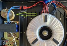
Completely out of subject, but this image shows a collection of bad practices:
And you didn't even mention them all. Look at those emitter resistors mounted vertically, flapping in the breeze. Put the whole thing down a little too hard on the counter, and the first copper traces will start to break. Likewise the vertically mounted LM317 with just a couple millimeters between its tab and two uninsulated vertical resistor legs right behind it. Not using a heat sink on a TO220 voltage regulator is something I'd try to avoid, just like placing electrolytics close to any hot running semiconductor (which would'nt run as hot if a heatsink was used, which might provide some mechanical rigidity at the same time, if done right.).
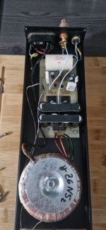
On a bigger picture, the whole internal layout of that amp is rather sub-optimal. It basically resembles a huge ground loop around the whole perimeter of the case. Maybe that's why it has some XLR sockets fitted after the fact, because it was unusable with RCA connectors?
The most effective hum-radiating antenna is the secondary wiring from the transformer to the reservoir caps, carrying the highest currents even when the amp is just idling. Look how much loop area there is from the reservoir caps of one channel, to the rectifier, to the transformer secondary, on to the other channel's rectifier, and finally reservoir caps. Neatly spaced out as far as possible, where it should have been the exact opposite: keep this area and the wire lengths to a minimum!
There's a nice guide out there covering grounding issues in power amplifiers. IIRC it was from hifisonix, who's even an active member here.
So interestingly the “upgraded“ version of this amp uses a Mundorf MCap EVO Aluminum Oil 4.7uf and swaps the AD711 op-amp for a Burson discrete. I’m basically wanting to do this same with Jupiter cap and sparkos discrete.
TO was talking about swapping the integrated for a discrete. I don't know how much idle current a Burson or a Sparkos needs, but since we're talking High-End already, the current draw might be at the high end, too.

Use any contemporary power transistor. I have an early schematic somewhere.
Don't wait too long with ordering as prices only go up and many discrete parts are being discontinued. I noticed it this week again when I ordered parts.
I know, its horrible since the last few years…
Also standard parts are often gone or have a very long leading time
Also standard parts are often gone or have a very long leading time
Yes. Standard parts that are now not longer standard😀
Mini toroids (sub 25VA) with lead wires for chassis mounting for instance. Gone.
Mini toroids (sub 25VA) with lead wires for chassis mounting for instance. Gone.
Have you found one? 🙏Use any contemporary power transistor. I have an early schematic somewhere.
Regards
Alex
Could you provide schematic, did any one try to use smaller value of capacitor. In my E1 is 10 uF Mundorf.Use any contemporary power transistor. I have an early schematic somewhere.
Attachments
- Home
- Design & Build
- Parts
- Can someone identify this part?