So I traced the Problem to fake BD139/140.
I had two brands one was marked NXP the other was marked CDIL
Swapped out the NXP and problem went away.
With my Phone the max output Im getting from the amp was 6 volts RMS with 20-0-20 transformer.
I can take the input voltage upto pk-pk voltage 2.4v (RMS of 760mv) before I see clipping. At this point the output under load is 16 volts RMS.
Yes Jan Pictures are nice. I will add some. Next plan is to start swapping transistors and see how it impacts sound and distortion so far I have tried 2n2222 and BC547B.
I have also tried playing with the biasing from .1mv to 50mv to 150mv. Playing with the Bias. Seems to have no impact on the FFT noise measurements.
Im disappointed with the output. The next up transformer is 40 volts. Maybe I will give it a try.
Fake parts are a big problem. I need to build some kind of Test Gig where I can test transistors.
As in what voltage and what amps it can do.
The hint for the fake BD was it had a HFE off 390. The replacement I used from CDIL was 170 hfe.
The Zobel with 10 ohms and 150 Nf cap seems to do a good job of clamping anything above 21 Khz. I need to brush up on how to bias resistors. The good news is AI will give you all the resistor values needed if you give it hfe and voltage. When swapping out the TO92 transistors. And trying different resistors do I really need to re-bias each and every transistor ?
The BC and 2N2222 seemed to work fine. One channel is my reference side the other is my test side.
If I get one combination to give less distortion and good sound. That becomes my new left channel and I experiment on the right to try and beat it.
Maybe I should try the larger transformer what could go wrong lol. Will post some pics of the lowest distortion I could get so far.
Last edited:
I never have problems with fake parts, not one in at least 40 years.
You know why?
At any rate, a difference of 340 or 170 in Hfe in a good design is not relevant and does not make the transistor fake.
And the 390 Hfe is much better than 170 so by your reasoning the CDIL was fake.
Jan
You know why?
At any rate, a difference of 340 or 170 in Hfe in a good design is not relevant and does not make the transistor fake.
And the 390 Hfe is much better than 170 so by your reasoning the CDIL was fake.
Jan
The hfe numbers were just an observation. For me the clue was that the harmonic distortion on the FFT screen vanished after I replaced the BD.
You never had a problem with fakes because you live in a developed country. Or you have the paperwork needed to buy from big companies like RS and Mouser. And you can afford to pay the extra it costs.
If you really want to help.
How about coming up with a simple circuit that will help us identify fake transistors.
I found one which allows you to measure transistor noise but its overly complex.
Ive scanned the site for ideas but could not find anything.
A simple transistor along the lines of the simple 1 transistor amps you see on youtube. Which can be pushed by a bench supply.
A curve tracer maybe? Rather than trying to re invent the wheel I think it's best to have a look at what others have done. People who make them tend to shoot for gold rather than what is usually actually needed or produce something that has very limited current and voltage limitations. This one has
http://techdoc.kvindesland.no/radio/complex_measurements/20051028154625797.pdf
But has some interesting ideas. So what to change while retaining the simplicity. The worst aspect it has is a current step generator. Power etc depends on the ramp drive voltage and current capability.
http://techdoc.kvindesland.no/radio/complex_measurements/20051028154625797.pdf
But has some interesting ideas. So what to change while retaining the simplicity. The worst aspect it has is a current step generator. Power etc depends on the ramp drive voltage and current capability.
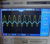
Ok I did a search. Question why would one half of a wave form be more than the other.
Same PA3 type amp.
Distortion sorted out. But now new problem.
The top wave form looks more than the bottom.
My noob understanding of it is that the PNP final driver transistor is doing a better job at amplifying than my NPN transistor.
So how do I fix this.
What are the parts in the circuit whose job it is to balance this.
Things I tried.
1. Swapping the wires around on the transformer output.
2. Trying larger and smaller transistors.
3. Different input sources and swapping the channels of the input source right to left.
4. Trying with larger and smaller input signals. (If pushed the top waveform clips first).
5. Monitoring the voltage of each rail. Both are perfectly matched.
6. Playing with the Bias trim pot all the way from 0mv to 150Mv. (If I take it much higher my Lamp starts to glow so I back off). The funny thing is no matter what I do to the Bias setting zero / 10/20/50/100 mv. I can not see anything
change on the scope signal. There is some minor change in the FFT analysis screen only.
Oops I just realised scope is in d/c mode. I have the same issue in a/c mode also. Will change the mode to a/c and take a fresh pic.
Attachments
Well if you zeroed the trace first it's showing where the signal actually sits. If DC mode is used generally the trace will usually be zeroed before it is used.Oops I just realised scope is in d/c mode
Im taking a break from Audio.
A kind of love hate relationship.
I spent a week trying to lower THD by trying different components and transistors.
After spending days on this I threw up my hands and walked away. It was then that I saw noise go flat.
Approaching the bench and walking away from it was impacting FFT values.
Im wasting my time here till I figure out how to solve such problems.
- Home
- General Interest
- Everything Else
- Can somebody explain this scope pic?