I got this from this site Why do some electrolytic capacitors increase in capacitance with age? - Electrical Engineering Stack Exchange
"If the voltage is too high the insulation layer will widen and capacitance will fall; too low the insulation layer shrinks and capacitance grows."
"If the voltage is too high the insulation layer will widen and capacitance will fall; too low the insulation layer shrinks and capacitance grows."
-/+8db is fairly mild and so you would only notice extreme hf getting boosted or cut, same for the low frequencies. So I would say normal.
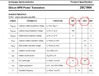
hFE is revealing but its little more than a comparison when done on a simple meter. To check the value against a data sheet involves using the same test currents as the manufacturer.
hFE is revealing but its little more than a comparison when done on a simple meter. To check the value against a data sheet involves using the same test currents as the manufacturer.
I've just checked some CDIL brand MJE340's and they come in at around 150. The actual value (high or low) will not alter the circuit performance due to the overriding influence of negative feedback.
Now it could be Elna's were produced with a 10% higher value than stated to cope with a less developed manufacturing technique that existed in the 70's, or to account for variation and drift. But if modern day manufacturers are producing caps with lower than stated values does that mean we are re-capping with to lower values?
That's cool Mooly you really made an effort to help. If this was your unit would you change that component?
The deciding factor is whether the cap meets the published specs. Old caps often had poor tolerance and +50%/ -20% was pretty common on larger values.
40uF vs 47uF might sound a big difference, but the effect on the response of the circuit will be minimal, and more than made up for by having a modern component fitted.
40uF vs 47uF might sound a big difference, but the effect on the response of the circuit will be minimal, and more than made up for by having a modern component fitted.
That's cool Mooly you really made an effort to help. If this was your unit would you change that component?
Having taken it out and mauled it around 😀, yes I would change it.
What I would also do is run a test signal through the amp (say 20kHz square wave) and look the difference (if any) that fitting a different part made by observing the two channels on a dual trace scope and overlaying the two outputs from that device. (Tests like that are always done with no speaker attached)
I don't think you will see any measurable difference though.
I wouldn't foresee any issues.
(And for the cost involved, why not get the original devices from Nikko).
(And for the cost involved, why not get the original devices from Nikko).
I think i would meet people both ways and change it for the same one, that way i would not have to change the other as well. Also the schematic states it is a fujitsu part as well, not sure what the B, V in brackets means perhaps you could have a look at this page and tell me what you think. That link you sent me looks like the right place. £7.00 posted though. Thanks.
Attachments
Japanese devices often had prefixes for gain (or sometimes gain grouping to ensure they were within a certain range) or voltage rating.
This shows just how much spread there can be on a device like this. If you get a few modern MJE340's you could select the best ones, but tbh, they should all be decent.
This shows just how much spread there can be on a device like this. If you get a few modern MJE340's you could select the best ones, but tbh, they should all be decent.
Attachments
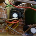
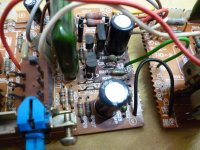
If it is corrosion, that green material would obviously be a powdery layer and the sign of a copper alloy underneath, the tinning on the metal having been eroded completely in that area. So if it is corrosion, a light rub with an abrasive pad like 'scotch-brite' will show a pink to bronze colour underneath that area. If not, then it isn't corrosion and you are fretting over a non-problem. In either case, just remove the excess flux and green material and polish the leads for the full exposed length. Then re-tin them without dallying about too long, refit the transistor(s) and leave well enough alone if it works.
On the other hand, if you believe that new components will give you peace of mind, then buy what you must - as near to original spec. as possible or as suggested by Mooly.
edit: to be precise, there probably never was any tinning at the top of the leads because it's hard to process tin them close to the package - hence the slight amount of corrosion which is common with bare copper alloys in moist environments.
Last edited:
The builders were conscious of that and so lacquered these locations. This is lacquer, not corrosion.edit: to be precise, there probably never was any tinning at the top of the leads because it's hard to process tin them close to the package
Not so sure I'd be happy with that. Glues and anti damping compounds that seemed a good idea way back at the time could possibly cause problems today as the materials break down and become (possibly... it does certainly happen) conductive.
- Status
- Not open for further replies.
- Home
- Design & Build
- Parts
- Can some one help me with this replacement part? Please