Can some one give me a schematic on a current source, adjustable around 3 A. I’m going to have it in the output stage, current stage in a power amp, to drive the speaker output.
A good current sink which can dip to within a volt of the rail can be made with two green LEDs, a 0R22 5W resistor, and an IRFP150.
This is a current sink, located at ground. For one supported from the rail, invert devices to an IRFP9140.
The two LEDs are run in series at around 2V each from the positive rail via a dropper resistor, dimensioned to give 4mA.
An electrolytic around 47uF is placed across the two LEDs to kill noise.
A 220R stopper resistor is passed from the anode of the upper LED to the gate of the mosfet. A 12V zener is placed (kathod uppermost) from gate to ground to protect against gate spikes.
The source is connected to ground via the 0R22 resistor.
The CCS output is the drain of the mosfet. Current can be adjusted by altering the value of the dropper resistor on the LEDs. For a 24V rail, start around 4K7.
The advantage of a mosfet here is thermal reliability and positive tempco over about 300mA. These devices are far superior from the POV of thermal abuse, since as they get hotter the current reduces, rather than increases as it does with bipolar devices.
Cheers,
Hugh
What plays we are game now, Hugh ? Exist many primitive circuits,which we can take " as standard ". I'm so tired, to explain it to beginers again and again....
No game, Epops,
This is a simple circuit which works well. That was what the guy asked; I explained it as best I can. What exactly is the problem? Are you criticising, or participating - it is not clear.
Hugh
This is a simple circuit which works well. That was what the guy asked; I explained it as best I can. What exactly is the problem? Are you criticising, or participating - it is not clear.
Hugh
Hi Progg70,
I guess you are going to build a SE output stage?
Attached I will cheer my idea of a CCS that is far more superior regarding current and thermal stability.
I checked the suggested FET IRFP150 by Hugh and think you should not just fix the gate to a voltage refference, this is because the FET change the Vgs so dramatically by temperature.
The datasheet I looked up is Fairchilds counterpart and for a given Vgs at 25 C degrees corresponding to 3 A you will have 8A at 175 C degrees which can lead to thermal runaway.
Now you wont probably experience such a high temperature change but this shows how bad it is to use FET's as CCS with a constant gate voltage.
The positive tempco of Rdson will never compensate for that as it is not working fully saturated state but rather in it's linear region, so that's why you need adding a device supervising the current, this is done as in my drawing by Q1.
Moreover it will also compensate for all kind of deviations like changing current by Vds changes (eg. your music signal).
However I deeply agree with Hugh to use FET's because of their robustnes and easy driving.
You will actually have a slight negative temperature coefficient when Q1 becomes warmer of surrounding components when the output power grows which might be welcome.
With R1 0,22 Ohm you will have around 3A.
Q2 is your own choice, but Hugh's suggestion is fine.
Cheers Michael
EDIT: btw, Hugh, are anyone of us misunderstanding what Progg70 want's? 🙁
Attachments
Michael,
It's not clear precisely what Progg70 wants; the voltage at the rail, the swing required, etc.
I agree your bipolar sensing network is superior from a current stability POV, no question. However, I've used a couple of the IRFP150s in parallel with 2 x 0R47 source resistors referenced from a couple of LEDs for about ten years on one of my amps and it is absolutely stable and settles very nicely at 2.8A total.
I earlier used your bipolar drive approach, but found the LED solution was no less consistent after warming up and there are visual indicators of operation!
Of course, you could combine both systems easily......
Cheers,
Hugh
AKSA said:Of course, you could combine both systems easily......
Cheers, Hugh
Yes! 🙂
And if we would make a combination with LED's, I would put it "above" the gate instead of "below"! 😉
I just want to clarify and add some further comments to my previous post, I mentioned:
I should say that above statement is valid when there's no source resistor, when we have a source resistor the problem is of course not that severe, just for Progg70's information.The datasheet I looked up is Fairchilds counterpart and for a given Vgs at 25 C degrees corresponding to 3 A you will have 8A at 175 C degrees which can lead to thermal runaway.
Cheers Michael
Yes it’s corrected that I want to build a Single-end power amplifier, (I guess you are going to build a SE output stage?).
I’m really glad people answer my question. I’m going to look on your recommendations.
What happens if you don’t have the series resistor and have a bias voltage on the current transistor that then opens up and then you have a current floating true it?
See the picture
I’m really glad people answer my question. I’m going to look on your recommendations.
What happens if you don’t have the series resistor and have a bias voltage on the current transistor that then opens up and then you have a current floating true it?
See the picture
Attachments
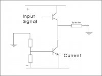
You will get thermal runaway in that case. When the transistor gets hotter you will get a higher current for the same Vbe voltage, which means it will get even hotter and the current will be even higher ...
What about the main task as current source, load for the audio signal?
If it would work; would it work nice then? or what is the bad with it in the perspective of the audio signal.
regard
😉
If it would work; would it work nice then? or what is the bad with it in the perspective of the audio signal.
regard
😉
Please is there some one who can give me some more information how the signal influence, bad or good in my schematic.
Please don’t waste you’re time on really bad answers Upupa 😡
Please don’t waste you’re time on really bad answers Upupa 😡
Why do you complain? Upupas answer was bold an honest, as usual. He gave an opinioin on the topology. If you don't care about his opinion, just ignore it.
Progg, if you do some googling about
"constant current source"
"current mirror"
"wilson current mirror"
you might find something
The thing you have drawn has poor temp stability, probably poor speed, probably unlinear also.
I think using a mosfet is the best but you won't hardly get any ready solution. You could check Nelson Pass class A amps. There you have current sources of several amperes.
EDIT: Ultima Thule's circuit might be something but the problem is also the front end!
Why bad ? It is true answer... All single ended amps have similar sound, 'cos they are single ended. Becouse NP's ones are most known, it was given as example...But ofcourse, you can't belive me... 😉
All single ended amps have similar sound, 'cos they are single ended
So all PP amps sounds the same too, cause they´re PP?
I have searched a lot and I found only basic description about Current sources, and nothing about high current sources.
I had some good examples earlier in this thread I can use, but now I’m curious about the mechanism how it works and how different solutions influence the signal and sound in a practical, objective way off fact.
I hope some one can give me a more direct URL to good stuff or have the information himself. It’s always nice to get in touch with people who know what and way the doing thing there way.
- Status
- Not open for further replies.
- Home
- Amplifiers
- Solid State
- Can some one give me a schematic on a current source, adjustable around 3 A.