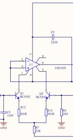
I refer to the circuit of the MVT preamp of musical fidelity of the 80's. Some threads about it can be found here on diycom. It concerns the line stage which uses a LM318 IC at the input. Special about it is that the input stage of the IC is disabled and taken over by a discrete input stage as can be seen in the attachment (done so according to original application notes of the LM318).
Now my question is: can the LM318 and associated components as used in this circuit be changed into a 'normal' differential amp with just resistors of resistors/transistors. The change I intented to bring about can be seen in the other attachment. The idea is that I use an empty IC-socket and solder the few discrete components onto it and then replace the LM318.
I simulated the new circuit and the results were fine, so I think it should work. Then I built the little thing and did the test for real into the existing preamp. Well, no sound at all, it didn't work.
Aside from practical errors in soldering etc: could this idea/principle work in practice? If no: why not? If yes: what did I do wrong?
Attachments
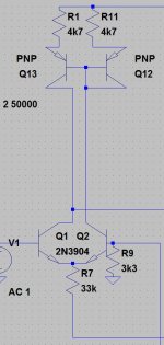
Its just a current mirror.
I use the same circuit in one of my amps and I made r11 a preset to adjust output dc offset.
I use the same circuit in one of my amps and I made r11 a preset to adjust output dc offset.
Like this
Thank you.
So it should work (as simulation confirmes).
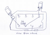
For sake of clarity, here the hand-drawing of how I wired the components. Just 2 resistors (4k7) and 2 transistors (BC560) put onto the IC-socket.
So why doesn't this work in my case?
LM318 in place: works allright
Like attachment: no sound
Thank you.
So it should work (as simulation confirmes).
For sake of clarity, here the hand-drawing of how I wired the components. Just 2 resistors (4k7) and 2 transistors (BC560) put onto the IC-socket.
So why doesn't this work in my case?
LM318 in place: works allright
Like attachment: no sound
Attachments
But you need to buffer the output of the current mirror with an emitter follower at least, to provide a low output impedance. The output impedance of the discrete component circuit you show will be extremely high, so the signal level at the output will get loaded down by the input impedance of whatever it is driving.
buffer stage
Well, the output (pin 6 of IC) is not the actual output of the total preamp. In between is a class-A buffer with push-pull BD139/140 driven by an intermediate stage.
http://www.diyaudio.com/forums/solid-state/77563-musical-fidelity-mvt-mk3-preamp-line-stage.html
So this should not be a real problem I guess?
At a quick glance I would remove the IC and all components and fit a modern opamp using keeping the same feedback and input network only. Link pin 6 to the output and use the normal -/+ inputs of the device. I'd even go so far as to suggest an OPA604 opamp as I still find these are sonically top performers.
- Status
- Not open for further replies.