Hi there,
I am interested in having channel switching in my guitar preamp. Here is the idea I came up with to switch from distorted to clean channel. Is this ok to do? I was wondering if its a bad idea to do this or if there will be a significant pop when switching channels. I'm trying to build the circuit as simple as possible with fewest part count.
Please give any practical advice about this.
Thanks all
Attachments
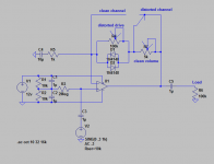
Looks OK. The important thing with switching components in a feedback loop is to not leave the opamp floating, even momentarily. So this is OK. You will get at least some noise as the switch is operated but that is unavoidable where there is a sudden step change in gain.
Try it.
Try it.
Which kind of switch will you use? Mechanical or CMOS? CMOS (like 4051/2/3 or 4066) have no bouncing and less noisier.
What configuration is better for op amp input, input using virtual ground or biasing?
Thank you Osvaldo and Mooly,
I was planning on a mechanical switch, I am not familiar with those CMOS switches, but I will look them up and study them.
And here is one more question about op amp circuits.
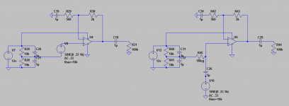
On the attached image, which configuration is better, the one on the left or right? In the schematic it is shown as an ac voltage, but in reality it will be a 1/4" jack mounted to a metal faceplate. So I was thinking the schematic to the right is better, because otherwise the faceplate would be at 6 volts (virtual ground I think its called) as referenced to the power supply ground. I really don't have practical experience but this seems like the right schematic is the better choice, I'm assuming that is more common.
Thank you Osvaldo and Mooly,
I was planning on a mechanical switch, I am not familiar with those CMOS switches, but I will look them up and study them.
And here is one more question about op amp circuits.
On the attached image, which configuration is better, the one on the left or right? In the schematic it is shown as an ac voltage, but in reality it will be a 1/4" jack mounted to a metal faceplate. So I was thinking the schematic to the right is better, because otherwise the faceplate would be at 6 volts (virtual ground I think its called) as referenced to the power supply ground. I really don't have practical experience but this seems like the right schematic is the better choice, I'm assuming that is more common.
Attachments
> the faceplate would be at 6 volts
Usually the wrong choice.
Also it "assumes" the input conducts DC (to cover opamp input current). A naked guitar usually does. Pedals, or active pickups, sometimes do not.
Usually the wrong choice.
Also it "assumes" the input conducts DC (to cover opamp input current). A naked guitar usually does. Pedals, or active pickups, sometimes do not.
Agreed that having the faceplate at 6 volts is a bad idea generally. There are totally isolated plastic jack sockets though.
The one on the right, definitely.
You do NOT want any DC voltage applied to audio ground, even less such a high value as 6V.
And you want to refer your audio ground to real ground, rather than a floating one.
As a side note, the NFB resistor values shown will work, no doubt, but are quite low compared to standard practice; 10X higher would be more usual.
CMOS switchs have the advantage of being high input impedances devices (from the point of view of the comand line) and that this command may be earted to signals, the you can use as long cables to switch the device as you want, also you can use delays, a microprocessor ar any other logic to switch the audio path. They are very easy to use, search for the data sheets for complete info.
> Agreed that having the faceplate at 6 volts is a bad idea generally. There are totally isolated plastic jack sockets though.
Now the guitar cord shells and "grounded" guitar parts are at +6V.
While 6V in 10K is far from "lethal", it's just Bad Form.
Still have the issue of not-all sources being DC conductive.
And that if the guitar or cord outside metal touches another ground, the signal shorts out. We have enough problems with shorts already, without making it easier.
Many many things work on paper (computer). THE convention in audio interfacing is no DC on the hot lead and really-no DC on the shell.
An R and a C don't cost that much.
Hi,
Try two diodes in series in one direction and one diode in the other
wired in parallel. This should give more even harmonic distortion
than two symmetrical diodes, which give odd harmonic distortion.
Its not my field, but there is a whole world of diode stacks for
controlling distortion if you include diode series resistors.
rgds, sreten.
- Status
- Not open for further replies.
- Home
- Live Sound
- Instruments and Amps
- Can I use 1 op amp with channel switching preamp