The only thing I would do is move the components across the AC line to the transformer side of the fuse...if one of those caps shorts out, the most damage will be a blown fuse. Unfused components across the wall plug should be a matter of concern....
This is incredible. Do you people understand that such equipment has to follow code to be allowed on the market? That normally one or more items will be tested, often to destruction, at UL or other authorized test labs, for safety and hazards before being unleashed on the public?
And now some audio diy guys with no formal education and less common sense think they can do better then all these test houses?
You guys know enough to be dangerous. Really dangerous.
Jan
The reason for the resistor is that high voltage can develop on an outside antenna from static electricity. The resistor drains it off; otherwise it would arc over periodically wherever the insulation is weakest - likely inside the power transformer. Not needed with a 3-wire cord; there's a path to ground. The 200 microamps passed by the line-ground caps is not a hazard. the 120 microamps passed by the resistor is less.
The reason for the resistor is that high voltage can develop on an outside antenna from static electricity. The resistor drains it off; otherwise it would arc over periodically wherever the insulation is weakest - likely inside the power transformer. Not needed with a 3-wire cord; there's a path to ground. The 200 µA passed by the line-ground caps is not a hazard. the 120 µA passed by the resistor is less.
… which is a nice quantitatively competent way of saying, “it (the resistor) was designed into the circuit for a bonafide reason, and thus it really should be left there, doing its designed-in job.”
⋅-=≡ GoatGuy ✓ ≡=-⋅
Yes, but at least the reasoning behind it - the why - is answered 🙂 Thanks, Tom.
I guess this is from the times of "two caps and a resistor is cheaper than house ground"? I've never seen this in practice on anything I've effed with...
I do know now that those caps are why you feel a 60Hz buzz when you brush the metal front of an old receiver with the back of your hand or arm 🙂
I guess this is from the times of "two caps and a resistor is cheaper than house ground"? I've never seen this in practice on anything I've effed with...
I do know now that those caps are why you feel a 60Hz buzz when you brush the metal front of an old receiver with the back of your hand or arm 🙂
If the resistor is somehow a weak link. Just replace it with a modern 1Mohm 3.5kV high voltage metal film resistor. Cost 30c. Or there are also flame proof or non-flammable ones (with voltage rating 350 to 750V, from 0.6 to 3W power ratings).
Why replace it ? Just remove it and the "security caps" .If the resistor is somehow a weak link. Just replace it with a modern 1Mohm 3.5kV high voltage metal film resistor. Cost 30c. Or there are also flame proof or non-flammable ones (with voltage rating 350 to 750V, from 0.6 to 3W power ratings).
It looks to be a safety feature to discharge the caps and stop the user getting a little shock from the mains plug... which is very common actually. Those caps are tiddlers, its more of a problem with 0.22uF or 0.47uF caps which have been used in the past in some equipment. Those can give a nip to the unwary.
I don't understand discharging the caps. Isn't it AC from the plug? If that was my unit I would remove both
caps and the resistor and then put an RC snubber across the switch. The 2 caps are treating the AC line as if
it's balanced and it is not. What it guarantees is the chassis will be 1/2 of the line Voltage without the 1 meg
resistor. The reactance calculator says the .005 uFd cap is 637K at 50 Hz so the 1meg resistor will imbalance
the caps, possibly why (at least in the States) you would reverse the line plug to get least hum. (WAY back before
polarized plugs and proper safety laws)
That kind of connection with the caps is what you would find in the AC line filters. Plug in 100 machines (I
worked at a video facility that had over 500 units with those filters) and you get a nasty loop current into the
ground. What they did was to use 120 Volt balanced. Now you need dual breakers and twice the wiring as
there is no neutral and transformers with center taps to get 60-0-60 supplies. BUT you also get no hum. If you
look at the medical grade line filters, the only difference is instead of 1 cap each from line and neutral to
ground, there is 1 cap line to neutral and nothing to ground.
G²
Ampex . . . a well known and trusted corporation.
I am sure that the tuner as it was designed many decades ago met all the safety regulations at the time it was produced.
The product is "Grandfathered" in.
It probably had a UL sticker on the original power cord (usually removed by the owner),
or on the back panel.
I have worked with UL over the years, and with a major corporation that worked with UL over the years.
You can second guess something that was designed, and passed UL decades ago.
It quite possibly would not pass as a Brand New product design, because safety regulations changed over the decades.
If you modify the mains power input circuitry of a "grandfathered" product, please be sure that it will pass todays safety regulations.
And . . .
Get it inspected and approved by UL.
Otherwise, if anything goes wrong, the lawyers will be more than willing to make you pay.
I am not saying that your lawyer will not be able to win your case (If your modifications make it safe),
but who wants to pay a lawyer (not an issue if you have your own corporate lawyer who is currently just spinning his thumbs).
The proper american language word are: May I remove, or Should I remove, not Can I remove.
Last edited:
That resistor is oddly placed. Unless I'm missing something, it would make more sense to put it from live to neutral, not live to earth. It would discharge the caps either way. For that matter, shouldn't the caps be placed across the transformer primary so they suppress flyback when the switch is opened? (they would also discharge through the primary winding with no need for the resistor).
Here is another reason: When the AC plug is being connected or disconnected, the contact never establishes in ideal manner. It is a series of makes-and-breaks instead. At a certain point the capacitors are charged at AC peak. When there is a short break and another make of contact after one full cycle (16 ms), the capacitor may charge at double AC peak, which it is not designed for. The resistor could bleed it to safe voltage within one cycle, so the next peak will find it at low initial voltage.
Here is another reason: When the AC plug is being connected or disconnected, the contact never establishes in ideal manner. It is a series of makes-and-breaks instead. At a certain point the capacitors are charged at AC peak. When there is a short break and another make of contact after one full cycle (16 ms), the capacitor may charge at double AC peak, which it is not designed for. The resistor could bleed it to safe voltage within one cycle, so the next peak will find it at low initial voltage.
Those caps are rated at 1400VDC! Come on. And obviously the 1M won't drain the cap in one cycle. Otherwise what's the point of putting them there?!
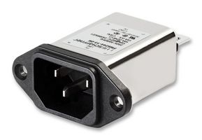
Like this?
https://canada.newark.com/schaffner...nents-EMC-RFI-Suppression-Suppression-Filters
An externally hosted image should be here but it was not working when we last tested it.
https://canada.newark.com/schaffner...nents-EMC-RFI-Suppression-Suppression-Filters
So your advice is to put a proper 3 wire power cord on it, then spend $5000 on a UL inspection?If you modify the mains power input circuitry of a "grandfathered" product, please be sure that it will pass todays safety regulations.
And . . .
Get it inspected and approved by UL.
As always, work on Vacuum Tube Amplifiers and such at your own risk.
Tuners too; even solid state . . . if you turn it off, but forget to unplug it, open it up, and get your hands inside . . . Shocking!
I doubt anybody is going to end up with a lawsuit on their desk because of doing mods to that Ampex tuner.
But saying that they did it wrong decades ago is a little harsh.
First of all, most homes back then did not have 3 wire mains power system outlets in their homes, right?
And a lot of people used those '2 wire to 3 wire adapters' on their 3 wire amplifiers in houses that had 2 wire outlets.
How about the 3 wire Refrigerator?
How many of you with that 2 wire to 3 wire adapter, actually connected the dangling wire to a good earth ground?
The right hand touched the water tap, and the left hand touched the metal handle on the refrigerator. I guess the right hand did not know what the left hand was doing.
I am just saying.
- Home
- Amplifiers
- Tubes / Valves
- Can I remove this 1meg resistor?