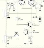
I have an old (and much beloved) K-12M tube amplifier - significantly upgraded from the original kit. I'm looking at my next set of modifications (adding a CCS to the cathode and an IR remote control) and was wondering if I could convert it to a balanced amplifier by changing the pre-amp wiring slightly. Here's my quick sketch on one channel - I'm picturing the + & - of the balanced line to be connected to the two points at "RIGHT IN".

(Pre-warning that I'm an electrical engineer who was schooled well after the days of tubes so I'm mashing some of my op-amp knowledge in here... likely poorly.) Wondering if someone could sanity check this for me - is this do-able and are my mad scribbles the way to do it? Would my pre-amplification losses, going from a 2-stage amp to a single differential stage, be worth the change or would it sacrifice too much? What would my R1/R3, and R2/R4 values be to set the gain as best as possible?
As a side note, I just noticed tonight that I've been running 10GV8 tubes on this rig for years (no idea how I came to that change)... they seem quite happy and sound awesome... but I would have thought they wouldn't like the higher grid voltage or cathode current and end up burning out pretty quickly (or letting the smoke out of some other part of the system). Is this weird?
I wouldn't call it balanced - it depends on matched gains and a truly balanced input - adding a transformer would be better.

InterestingI have an old (and much beloved) K-12M tube amplifier - significantly upgraded from the original kit. I'm looking at my next set of modifications (adding a CCS to the cathode and an IR remote control) and was wondering if I could convert it to a balanced amplifier by changing the pre-amp wiring slightly.
I love those vertical oscillator and output combo tubes.
I don't know if a ccs will auto trim bias.
Because you have to set up trimming the bias on at least one tube so you can match another.
Was this built point to point or do you have to modify a PC board?
This is a sample of a triode stage that has manual balance. I don't know if you can get a ccs to work that way:
...I agree with @Tom Bavis , adding a transformer to the input would be the most logical way to utilize a balanced input signal. Also the easiest, and quite likely the best sounding.
It would be the easiest way to do it. A lot of pro audio gear is made that way...I agree with @Tom Bavis , adding a transformer to the input would be the most logical way to utilize a balanced input signal. Also the easiest, and quite likely the best sounding.
Yeah, except that's not what he's asking about. Anybody can add a balanced input interface via a transformer. 🙂
He's asking about converting his existing amplifier to a balanced topology. As shown, (with the red lining) the phase-splitter is re-purposed into another input tube.
I don't see any problem with this. It should work.
Dave.
He's asking about converting his existing amplifier to a balanced topology. As shown, (with the red lining) the phase-splitter is re-purposed into another input tube.
I don't see any problem with this. It should work.
Dave.
Well, that's true enough...
Would it work? Yes, I think so. The question is, and has already been posed by OP is will there be enough gain to make it all work.
The K-12M is about as perfect a testbed for this as you could ask for. It's worth trying. (Though I'd still just use a transformer, but probably because I've got some laying around...)
I wonder what voltage they are running on the plate. Source would have to be pro level ( +24dbm)The K-12M is about as perfect a testbed for this as you could ask for. It's worth trying.
How much voltage gain do you think the phase-splitter supplies in the original design?? 🙂Would it work? Yes, I think so. The question is, and has already been posed by OP is will there be enough gain to make it all work.
Dave.
Use 6DJ8/ECC88 differential circuit. The common cathode connects to a LM317 CCS. Negative voltage supply isn't required.
Very simple but very effective.
Cool for balance input.
Johnny
Very simple but very effective.
Cool for balance input.
Johnny
Yes, didn't mention this second order issue. The parts that give you trouble are the ones that aren't on the schematic!
Would you consider a virtual ground by a pair of resistors across the output adequate? Depends on R value, I guess.
All good fortune,
Chris
All good fortune,
Chris
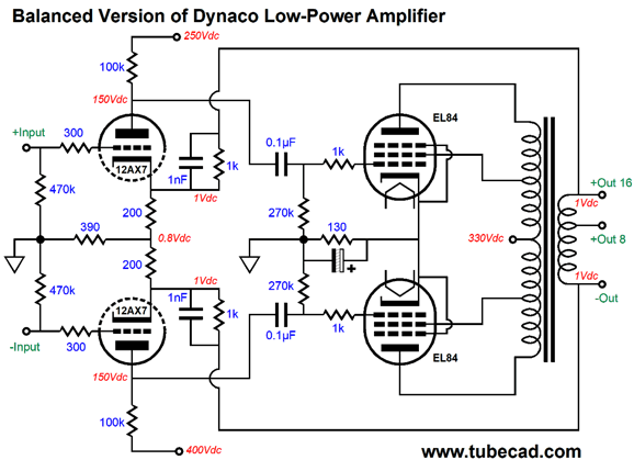
Seems like the OP is asking for a way to do balanced feedback in a power amp with single ended input. The split-load/cathodyne/concertina circuit makes it awkward because you have a 3 stage amp now without balanced paths. Without an input transformer to split the phase first it will be tricky. Assuming you don't want to use input transformer, you still need a phase splitter upfront. John Broskie suggested a balanced version of a Dynaco circuit without center tap on the OPT secondary, see picture below, which is routing the balanced feedback to the two cathodes and the two cathode resistors form a virtual center tap. It is still asking for phase splitter, though, like an input transformer or a split-load/cathodyne/concertina circuit upfront. But if you don't want to add input transformer nor extra tube, one way I can think of is to use a paraphase circuit like the Western Electric 124 but that can be a rather awkward circuit. There might be a circuit out there. It's a brain tease!
- Home
- Amplifiers
- Tubes / Valves
- Can I mod an unbalanced design to make it balanced?