Hi all 🙂
This is not a DIY amp project so I hope it is OK to post this question here. I am restoring and doing modest mods to a Kenwood KA-4006 integrated.
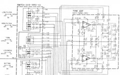
My question is in regards to caps Ci15 and Ci16 shown in the schematic attached. They are currently 100uF/10v. It would be just as easy to replace these with 220uF/10v as they are close to the same physical size as the original caps. I will be using Panasonic FM.
Could it be detrimental to this circuit to increase capacitance of these two caps? If so why? Could it be beneficial? Better power available to the opamp or better decoupling?
Thank in advance...
This is not a DIY amp project so I hope it is OK to post this question here. I am restoring and doing modest mods to a Kenwood KA-4006 integrated.
My question is in regards to caps Ci15 and Ci16 shown in the schematic attached. They are currently 100uF/10v. It would be just as easy to replace these with 220uF/10v as they are close to the same physical size as the original caps. I will be using Panasonic FM.
Could it be detrimental to this circuit to increase capacitance of these two caps? If so why? Could it be beneficial? Better power available to the opamp or better decoupling?
Thank in advance...
Attachments
They are power supply filter caps, so increasing the value should be fine. However, is there additional filter capacitance for the B+ and B- lines? If so, if might make better sonic sense to use a metalized polyproplyene of 10 uF. It is not so much the absolute value of capacitance, but the quality of the capacitance.
@ Jeff R
I believe (I am a bit noobish) that there is additional filter capacitance for the B+/B- lines on this board if you count the lines that supply this board...they come directly from a simple shunt regulator (14v zeners) with 470uF/16v electrolytics on the downstream side of the zeners. But there are 680R resistors, Ri26 and Ri27, between the other voltage source and the opamp. Does that mean anything? Is it easier for the opamp to draw from Ci15 and Ci16 than from the other caps? There has to be a reason they were put there by the designer, what was that reason?
I don't think 10uF of any type of poly will fit there. The 220uF Panasonic FM will fit just like the original 100uF. I am not looking for drastic improvements or putting in major effort. Like I said, physically, the new 220uF is about the same size as the original 100uF. Easy change. Just don't want to throw something out of whack.
Beside the role of power supply, do the caps in question, Ci15 and Ci16, also decouple the opamp?
Last edited:
The resistors decouple the op amp power supply. Theoretically, the resistors form a low pass filter (Ri28 with Ci16), reducing any voltage fluctuations on the input supply lines. In this case, you want lots of capacitance (i.e. Ci16) to supply transient power, as you can't get a lot of instantaneous current through the series resistors. That implies you need a good quality cap to supply high frequency current, since it can't come from the main power supply due to the resistors.
Using 220 uF won't cause a problem, though.
Using 220 uF won't cause a problem, though.
thank you Jeff R
After posting here I also posted this question, and some other related questions, at AudioKarma to get some additional opinions. Several members there agreed with you that it would be OK to increase from 100uF to 220uF on these two caps
After posting here I also posted this question, and some other related questions, at AudioKarma to get some additional opinions. Several members there agreed with you that it would be OK to increase from 100uF to 220uF on these two caps
At >20 years I would worry also about Ci1 and Ci2. These show to be electrolytic, and if they dry up they can distort the input sound. I've had this happen in my Sony 250 taperecorder I was using as a preamp, as well as my dynakit st120 power amp. You should force film caps in there even if you have to fly them above the pcb and lengthen the leads a little bit. You should also confirm Ci5 and Ci5 are not electrolytic (plus on one end or minus in balls pointing at one lead, or "np" after voltage) and if they are , change them too. These need to pretty well match the old ones. That is if you don't want to take the amp apart again and do it later. Electrolytics are like a "time fuse" that blows eventually.
On my ra88a disco mixer, the resistors in the local input section power rails were to reduce the hum from the power supply. The op amps were capable of taking the higher ps voltage, but hummed worse without the resistors, even with bigger caps at the op amps. Sloppy but cheap technique to reduce hum.
On my ra88a disco mixer, the resistors in the local input section power rails were to reduce the hum from the power supply. The op amps were capable of taking the higher ps voltage, but hummed worse without the resistors, even with bigger caps at the op amps. Sloppy but cheap technique to reduce hum.
Last edited:
Thanks indianajo, lots of good thoughts there...
(BTW, Anderson IN here)
RE: Ci1 and Ci2, these have already been replaced with Silmic II. In fact all of the electrolytics have been replaced, but I will be going back into this board again to exchange the new PW caps I used at Ci15 and Ci16 with FM, most likely of higher capacitance as was the original question in this thread.
Having had more time to think, and on your suggestion as well, I would like to put film at positions Ci1 and Ci2. I think a Wima MKP would actually fit there no problem. But I have some issues with the PCB traces on one of these and, because of that, will probably opt to leave the Silmic II's in place. The pad is very narrow and part of it simply flaked off and is gone. I would be afraid to do any more soldering there, as the current Silmic II cap appears to be solidly in place. Film would be nice, but I think I better leave well enough alone in this case.
Ci5 and Ci6 are indeed electrolytic. They are NP and have already been replaced with Nichicon Muse NP. Replacing those with film, although again, a good idea, may be impossible due to the layout of the board and space limitations. But I will double check this.
As far as mounting caps up off the board and extending the leads, I would be hesitant to do this as I have read warnings against this at Rod Elliot's site.
regards
Last edited:
Your new NP electrolytic caps should be good for another ten to twenty years, I wouldn't worry about redoing it now. Where'd you get them? Newark has no NP caps, Mouser lists Lelon as NP caps in the index, but nothing about that on the catalog page.
I flew a lot of film caps above the board on my Hammond organ, but those only go up to 8000 hz so I can't say it was successful at a full audio 20 khz. I also left the old leads in the board, cut the leads and hooked over the leads from the new caps. I don't like lifting traces off the pcb, do it more than necessary I'm sure.
Modern parts can oscillate with excess lead length. I had to stomp out a 1mhz oscillation on my Ra88a mixer when I replaced 4558 op amps (slow slew rate) with 33078 op amps (7 v/microsec slew rate).
The hammond does not have modern transistors.
Last edited:
Mouser has Nichicon ES series NP electros that are marketed as "Audio" type. I have read opinions in threads that these are good to use wherever a NP is required (unless you go to poly of course).
Link: Mouser Electronics - Electronic Component Distributor Aluminum Electrolytic Capacitors - Leaded
I just started at the full Mouser product list screen and worked my way down. You can see the path near the top of the screen in this link. This show all their NP electros. From there I would choose Nichicon for the manufacturer to narrow it down further, then look for the size needed in ES or "UES" to match the naming convention used.
See pic attached of Nichicon Audio cap line.
Regarding flying caps: The warning at the ESP site had something to do with increased inductance caused by the longer leads. It is recommended there to always keep cap leads as short as possible. But in your case...up to 8kHz only...you may be right and maybe this wouldn't be an issue. I do not know honestly.
Interesting that a mere 7v/uS slew rate caused oscillations. Although that is higher than the 4558's slew rate, it is still much lower than other current op amps (I am learning this practically as we speak...I am engaged in a similar thread at AK)
So how did you become aware of the oscillation in your mixer and how did you fix it?
.
Attachments
Last edited:
I had the RA88a op amp mixer plugged into a Peavey CS800s power amp with a 2 speed fan. At a certain volume (1.5 Vac out on speaker) the PAS2 preamp was running the fan at slow speed, the RA88a was running the fan at high speed. Even oscillating the 33078 op amps sounded better than the 4558's, which were hissy. I put the ra88a back on the oscilloscope and saw the oscillation. (B&K 2120, $40). I put 0.1 ceramic caps on the power supply rails, not good enough. I put 22 pf across the feedback resistor on the op amp, that killed the oscillation.
Then I started the hum war- the Ra88a hummed a lot worse than the PAS2 preamp. If you're interested in the whole war story, it is here http://www.diyaudio.com/forums/anal...improving-disco-mixer-mid-fi-performance.html
Mixer sounds so good now I put the PAS2 in the attic. The volume control is stuck, a purchase from the dynaco bankrupcy receiver.
Thanks...
In the other thread I mentioned I am investigating replacing my 4558's (or at least the one on the tone board, there is also one on the phono board) so your experience is relevant. I will most definitely read your thread, although I do have absolute confidence in the person helping me out over at AK.
The only stumbling block, at this point, is that I have no scope and no access to one. So you picked one up for $40? Did you get it on eBay? Did you have to repair it?
Last edited:
No, a Radio & TV school graduate fished some out of the dumpster as a student. He was cleaning out his repair shop and listed the B&K and some 20 mhz Hitachi's on craigslist. I drove over and took a transistor radio and some adapters to check out the display & sync. It worked. Still does. Probes are $50 each at mouser, but I had bought some HH Smith ones 20 years ago, so I'm in. You need a big banana plug for the ground wire, also.
I had a televideo tube scope I fished out of a dumpster previously because the power supply caught fire. Even repaired, the sync circuits were ****. They had been using it in the radio room, when I got it fixed, I found out why- sync was useless below some many Megahertz.
The computer repair shop in New Albany on Spring Street might still have the Hitachi's, he never listed them again on craigslist.
The 4558 is the major performance limiter here...
The TL072 would be an ideal replacement and should not have any stability issues. If you do swap the opamp I would advise you check the DC voltage on its supply pins as being resistively fed, any change in current draw by a different opamp will reflect in a change in supply. Something like an NE5532 (not really recommended here) could actually pull the supply down.
And 10 volts caps on 9 volt rails seems a strange commercial choice. Personally I would fit 16 volt caps. But that 4558 is a big performance killer...
@indianajo
I did read your thread. Very interesting, even though a lot of your troubleshooting steps went right over my head. Your electronics knowledge is far greater than mine.
Thanks for the tip re: the Hitachi scopes. That is a bit too far away for me to consider. Starting a new job next week and lots of things need doing before then. I don't know how to use a scope anyway.
@Mooly
Good to hear some confirmation that ditching the 4558 is a worthwhile endeavor. On my board the pin spacing will not allow a modern DIP8 package. My 4558 is a TO-99 and there are actually several choices of those available at Mouser. Not the one you suggested though. And I will note the relevant voltages should I proceed with the change. I do understand that any changes in current through this resistor would affect voltage powering the op amp.
----------------------------------------------------------
I have never started two threads on the same topic before...but I did so a couple days back asking whether it was OK to increase capacitance on Ci15, Ci16. One thread here first, then a few hours later one at AK. (FWIW, I don't think I will try that trick again, lol)
But it is interesting that both threads have drifted to the topic of the 4558...
Like I said before, the person helping me out over there is as good as they come, I am certain he will steer me in the right direction...
Last edited:
The choice of opamps in TO-99 is bigger than I thought (though there's only a handful of duals), but boy are the buggers spendy. LM4562s or LME49720s must be 3 times the price of their DIP-8 counterparts. Besides, I'm not sure whether they'd really be an update, considering the relatively high impedances in the circuit and their current noise density.
On my board the pin spacing will not allow a modern DIP8 package. My 4558 is a TO-99 and there are actually several choices of those available at Mouser......
I take it from what you say that the T099 4558 has not got the lead outs pre-formed into the DIP configuration but is mounted with the leads in a circular pattern. Sometimes PCB's can be made for both types (I mean having the print for both types on the board) perhaps with the unused one being left undrilled. Just a thought.
The LM4562 is the successor to the 5532 and would almost certainly require the supply feed resistors to be lowered to maintain supply voltage. It's a much better device too.
Actually, the TO-99's leads emanate from its body in a circular pattern. But the PCB through holes are arranged in a quasi-DIP-8 pattern. Along one side of the mounting holes the alignment is very close to the standard DIP-8. But across the other direction it is more narrow.
Picture is worth 1000 words, see attached. In a standard DIP-8 the distance from pin4 to pin5 (according to 5532 datasheet) is .43" In my non-standard layout, the distance of the holes from pin4 to pin5 is approximately .1875"
In order to replace my 4558's I am looking at two problems:
1) My non-standard opamp package. If there was an adapter or some way to fit a DIP-8 then of course my choices would be unlimited. But as mentioned previously, there are some TO-99's available including the LM4562 and the LME49720, both at around $20.
2) Another puzzle that must be solved, is incorporating a replacement op amp while avoiding any potential oscillation issues. And having no oscilloscope to verify lack of problems.
Regarding problem #2, as I am just starting to learn about opamps, I am wondering what is different about the newer devices, compared to the 4558, that would introduce the possibility of oscillation? I would assume that several generations of op amps have been developed since the 4558, and that parameters have improved dramatically across the board. Why do oscillation issues result when newer op amps replace older ones?
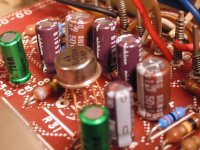
Pic attached is the tone board referred to my my original post. I have already recapped it but plan on going back in to change some caps and also add few more metal film resistors. @indianajo - the green caps are the Nichicon ES bipolars
Picture is worth 1000 words, see attached. In a standard DIP-8 the distance from pin4 to pin5 (according to 5532 datasheet) is .43" In my non-standard layout, the distance of the holes from pin4 to pin5 is approximately .1875"
In order to replace my 4558's I am looking at two problems:
1) My non-standard opamp package. If there was an adapter or some way to fit a DIP-8 then of course my choices would be unlimited. But as mentioned previously, there are some TO-99's available including the LM4562 and the LME49720, both at around $20.
2) Another puzzle that must be solved, is incorporating a replacement op amp while avoiding any potential oscillation issues. And having no oscilloscope to verify lack of problems.
Regarding problem #2, as I am just starting to learn about opamps, I am wondering what is different about the newer devices, compared to the 4558, that would introduce the possibility of oscillation? I would assume that several generations of op amps have been developed since the 4558, and that parameters have improved dramatically across the board. Why do oscillation issues result when newer op amps replace older ones?
Pic attached is the tone board referred to my my original post. I have already recapped it but plan on going back in to change some caps and also add few more metal film resistors. @indianajo - the green caps are the Nichicon ES bipolars
Attachments
Last edited:
Thanks for the pic...
Is it possible to re-drill the board and fit an IC socket perhaps wiring neatly just one row of the four pins. I'm guessing the print is pretty wide and with plenty of copper and not super fine traces.
Another possibility is to fit neat wire extensions preformed to fit and solder them to a replacement IC. Only takes minutes to do.
On the problem of oscillation...
something like the TL072 should be absolutely fine "as is". If you fitted a replacement with extended leads then I would recommend soldering a small cap in the 0.01uF to 0.1uF directly to the IC across pins 4 and 8.
You might find this interesting although I don't forsee any issues with your application,
http://www.diyaudio.com/forums/anal...u-have-checked-see-its-stable-havent-you.html
Oscillation problems occur because the newer designs are faster (higher bandwidth and much faster slew rates) and so stray capacitancre and inductance can act to form an oscillator. You won't have a problem with the TLO72
@ Mooly
Yes, I read your thread. Very informative and well delivered. The scope traces really drive it home. Also, you make an excellent point that oscillation can cause audible problems that are often blamed on the opamp.
It is a bit ironic that I am asking for advice, both here and at AK, to do exactly what you advise against: changing an opamp without having the benefit of a scope to check the results 😱 I have done a ton of restoration work on this amp - all fresh electrolytics, poly caps in key spots, metal film resistors in key spots, new bias trimmers, new relay and relay driver transistor, new differential input transistors, etc. Have now realized that the 4558 is a major weak link in my amp AND it is in the signal path at all times.
I have a couple more questions for you if you are game 🙂
---In post #14 you called the 4558 a "major performance limiter" and "a big performance killer". Would you elaborate on that a bit? Is this mainly because the 4558 is noisy? Or does it have other performance limitations compared to other opamps?
---Why would the TL072 be a good replacement candidate that would not cause oscillation issues? It does have 13v/uS slew rate compared to 1v/uS for the 4558. (although, as far as I can tell the bandwidth is the same on both)
---I have found a Texas Instruments RC4558 that has what looks to be a good spec for noise (Vn) of 8nV/SQRT(Hz) compared to 18nV for the TL072. Would this 4558 be an even safer replacement than the TL072?
Note1: Test conditions for these Vn numbers are close but not identical, spec sheets attached
Note2: I have been unable to determine the manufacturer of my original opamp (JRC4558) and have no Vn for comparison
---As another replacement potentially even safer than TL072, what about a 4559? The NJR 4558 and 4559 have the same specs except for both the slew rate and the bandwidth are doubled in the 4559 (from 1V/uS and 3mHz to 2V/uS and 6mHz)
I tried to attach TL072 and TI RC4558 spec sheets here but they exceed the allowable size limit. I would be happy to email them.
Attachments
Last edited:
- Status
- Not open for further replies.
- Home
- Amplifiers
- Solid State
- Can I increase capacitance on these TONE BOARD caps?