Folks:
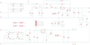
Please forgive what may well be a very dumb question, but I do need some advice. I am planning a Noval Aikido preamp project and have a power supply question. I have two Hammond transformers on hand -- a 369JX (50VA, 500V C.T. @ 69 ma and 6.3V C.T. @ 2.5A) and a 166L6 (12.6VA, 6.3V C.T. @ 2.0A). I understand the Aikido needs more heater current than the 369JX alone can supply. Can the 6.3VAC secondaries on both transformers be connected together at the power supply? I have attached a copy of the power supply circuit; the power supply board itself can be found at https://www.ebay.com/itm/144817864498
Regards,
Scott
Attachments
You can only parallel them safely with both windings on the same transformer.
Even then they should be identical windings, with the same current ratings.
Can you use one winding per stage or channel instead?
Or the windings could be in series with no problem, up to the lower current rating of the two,
if you can reconfigure the filament connections to use twice the voltage.
Even then they should be identical windings, with the same current ratings.
Can you use one winding per stage or channel instead?
Or the windings could be in series with no problem, up to the lower current rating of the two,
if you can reconfigure the filament connections to use twice the voltage.
rayma:
Thanks, but damn. The power supply board mentioned in my first post doesn't offer "dual mono" heater circuits, which would resolve my problem. I have the two Hammond transformers on hand and the next step up in that Hammond line is the 370JX, which has more than enough current for my application but costs $160+.
Maybe I'll keep the 369JX for the filaments and get something like a Hammond 266M12 (38VA, 6.3V@6A) or 266PA6 (37.8VA, 6.3V@6A) for the heaters. Hmmm..., there's also the 167Q6, which has a smaller footprint. They're all about a quarter the 370JX's price.
I appreciate the quick response!
Regards,
Scott

According to the schematic the 6.3 V AC goes only to a doubler.
If you connect the two 6.3V secondaries in series, you do no longer need the doubler, just the bridge.
All you have to do is to cut the trace which goes to the center tap between C5 and C6. Alternatively you could just remove C5 and C6 altogether and leave the PCB intact as is. With a bridge ripple is lower and less capacitance is needed.
This "trick" was used in those ATX computer PSUs which had a single switch to select 120 or 240 V mains input.
A side effect of turning the doubler into a bridge is that the load on the transformer is actually lower than before.
Last edited:
doesn't the Akido need 2 separate heater supplies? coz the cathodes are at wildly different voltages?
but ya, you wire the primaries of all your power transformers in Parallel to the Mains input. make sure everything is fused and switched. one heater supply will be referenced to ground, or a suitable low voltage, and the other will be referenced to the higher voltage, prob from a divider. you can use the center tap from the secondary windings, if provided, or just tie a 100ohm 1w resistor from each leg of the heater supply to your reference voltage, or Ground.
but ya, you wire the primaries of all your power transformers in Parallel to the Mains input. make sure everything is fused and switched. one heater supply will be referenced to ground, or a suitable low voltage, and the other will be referenced to the higher voltage, prob from a divider. you can use the center tap from the secondary windings, if provided, or just tie a 100ohm 1w resistor from each leg of the heater supply to your reference voltage, or Ground.
Last edited:
Why is that? What noval tubes are you planning to use and what Aikido version do you have. Doesn’t Aikido use two dual triodes tubes per channel, four tubes total?I understand the Aikido needs more heater current than the 369JX alone can supply.
Most noval tubes need only 300 ma at 6.3 volts, so your 2.5 amps supplied by the 369JX is probably sufficient. I have not seen recent Aikido build manuals so perhaps I’m missing something.
Four 300mA heaters is 1.2A at 6.3V DC, but that means about 2A rms, and with derating for the current peaks, a 4A rms Trafo is best, 3A rms at a pinch (and tested to see it doesn't get hot).
The HV supply is more troublesome. The Maida HV regulator design shows a number of flaws, including no attempt at frequency compensation. So the film cap directly across the output should be removed, if stable operation is desired, and likely will need a few ohms in series with the lytic.
If the anode supply winding is really 500V rms, I wouldn't want to apply it to a Maida whose standoff transistor is rated for 450V DC absolute max.
The SOA of the transistor allows only 20mA at 300V DC (Tc 25 ⁰C), so start up and shutdown events (and loading faults) need careful consideration, to be sure this doesn't blow up.
There's no antiparallel diode to protect the base-emitter junction of this transistor either (rookie error), and it could be damaged at shutdown or if the input gets shorted.
Sorry to be a doomster, but better to keep to low DC voltage with this one.
All good counsel -- thank you! In a wild bit of crazy good fortune, 6sX7 has a spare Glassware PS-21B kit which he has kindly offered to me. The PS-21B can accept two pairs of 6.3V heater secondaries, so I'll use both of the transformers I have on hand (Hammond 369JX and 166L6). Problem solved!
No-Load Voltage on the Hammond 369JX is 550v. Please be careful and build your power supply to withstand this voltage.
Sometimes it's best to start with the ideal transformer for the project instead of starting with the shoehorn in mind. But it's so hard not to.
Sometimes it's best to start with the ideal transformer for the project instead of starting with the shoehorn in mind. But it's so hard not to.
You can not connect transformer windings in parallel. Not. You can connect in series if the current rating is more or less equal. The rating of the series connection is equal to the winding with the lowest rating.
There is one exception to the first rule. If the transformers are identical you can parallel the same windings on each transformer. With identical I mean identical. Same type, same manufacturing batch.
There is one exception to the first rule. If the transformers are identical you can parallel the same windings on each transformer. With identical I mean identical. Same type, same manufacturing batch.
jlinkels:
Yes, I understand. The PS-21B board has three power supplies: one high voltage supply for the filaments and two low voltage supplies for the heaters. The 369JX will supply power for the filament supply and one of the low voltage supplies, and the 166L6 will provide power to the second low voltage supply. Unless anyone sees an issue with that approach, it appears I'm in good shape.
Thanks again to everyone for the advice (and 6sX7 for having the foresight to stock up on a power supply he doesn't need)!
Regards,
Scott
Transformers of different size/mfr are routinely paralleled every day in the utility industry.
As long as the per unit impedance of each transformer is within 5%, they will share load and have minimal var circulation between them. I have even run primary taps in different positions (turns ratio off by 2.5%) and they are just fine with a small derating based on reactive current flow. I am talking transformers rated in tens of MVA and voltages to 25 kV
Now, the OP may just want to not bother and stick to individual units, but transformer paralleling is not a scary process. Simple math and you can be confident of load sharing. Once you have the math under wraps, you can even get exotic and add a small series R or X to really get things dialed in.
That is correct. But that is slightly different from small transformers connected to a grid with virtually zero internal resistance. Before such utility transformers are paralleled I assume extensive studies are carried out based on the characteristics of those transformers.Transformers of different size/mfr are routinely paralleled every day in the utility industry.
As long as the per unit impedance of each transformer is within 5%, they will share load and have minimal var circulation between them. I have even run primary taps in different positions (turns ratio off by 2.5%) and they are just fine with a small derating based on reactive current flow. I am talking transformers rated in tens of MVA and voltages to 25 kV
In this forum I also would state asynchronous generators cannot be paralleled, while in reality it is done over the world to insert power into the grid. With carefully designed voltage and power regulation. So both voltage and power decrease with increasing reactive and real power respectively.
Best advice I got from my dad about x-former paralleling/load hogging and many questions related to electronics builds:
1. if you don't know and want to find out, be ready to handle a science project.
2. if you can't afford to do it right, you can't afford to replace your house.
In theory, many things can be done. In real-life, little gotchas await. Unless you have the test setup to monitor the load sharing and shutdown the PS accordingly, I would just go buy another transformer (or, in Scott's case, get a PS configuration that makes proper use of the x-formers he has on hand.)
- Home
- Amplifiers
- Tubes / Valves
- Can I Connect Two Transformers Together?