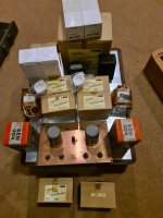
I'm planning to make a Phonostage with a Triode tube with an existing Hashimoto Transformer. This schematic is just a draft, with a Tamura TKS22 input with an Indirect Heather triode REN904 ( 20 - 30Mu) - Hashimoto Hl 20k (OTL) and Hashimoto EQL ( RIAA) amplifier and an AD1 DHT as preamp.
Can it run well? any suggestion? Thank You.
Can it run well? any suggestion? Thank You.
Attachments

The "typical" phono stage must -at least- has 40dB gain.
40dB = 100x (10mV in, 1V out).
Rough gain calculation:
SUT (9) * REN904 (20) * OT (0.17) * LCR RIAA (0.1) * AD1 (4) = 12.24
40dB = 100x (10mV in, 1V out).
Rough gain calculation:
SUT (9) * REN904 (20) * OT (0.17) * LCR RIAA (0.1) * AD1 (4) = 12.24

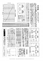
It is LCR RIAA , which have two coil , Low filter and High filter.Hashimoto EQL RIAA amplifier?
What is that? Where can I find the data?
Attachments
The "typical" phono stage must -at least- has 40dB gain.
40dB = 100x (10mV in, 1V out).
Rough gain calculation:
SUT (9) * REN904 (20) * OT (0.17) * LCR RIAA (0.1) * AD1 (4) = INPUT
Ah ! Looking at the data sheet it is a single (passive)RIAA filter not an amplifier.It is LCR RIAA , which have two coil , Low filter and High filter.
Wasn't aware of the existence of single RIAA filters. 😕
Gain:TKS22 have primary 32R : 50K.
SUT (39) * REN904 (20) * OT (0.17) * LCR RIAA (0.1) * AD1 (4) = 53
Need 100.
May be the gain structure will work, but AD1 sets limits concerning microphonie. And this AD1 sits quite early in the chain, so each tendencie for ringing will be amplified by the following components. Next problem: huming if you use AC for heating of the valve, I would choose constant current, but I am not absolutely sure if this will properly work. May be, AD1 is a batterie valve or better, intended to be heated by batterie. Same like RE604.
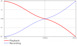
Is that the 20 Hz gain? The RIAA curve attenuates 20 kHz by 40 dB relative to 20 Hz.Need 100.
Attachments
It might be a senior moment but doesn't that imply the base required circuit gain is 60 dB to compensate for the 20 db RIAA attenuation at 1 kHz?
Every gain of Riaa is calulated at 1kHz.
And it is out of discussion that the Riaa de-emphasis circuit has 20 Hz at 20dB higher than 1 kHz and 20kHz are 20 dB lower
And it is out of discussion that the Riaa de-emphasis circuit has 20 Hz at 20dB higher than 1 kHz and 20kHz are 20 dB lower
With this ratio you have to select with a maximum care the Mc cartridge you connect; with a ratio of 39 the reflected impedance ( with standard load of 47k on phono input) is 30 ohm so you must connect a MC with 1-3 ohm.TKS22 have primary 32R : 50K.
At 1kHz both the "recording" and "playing" correction chain "gain" is at basic situation.
If you have -for example- 5mV RMS input, the 40db (100x) gain of phono equipment results 500mV RMS output signal (which is not too much).
If you have -for example- 5mV RMS input, the 40db (100x) gain of phono equipment results 500mV RMS output signal (which is not too much).
It can be considered a standard gain, because there is a line stage that amplify the signal and probably you add around 20 dBAt 1kHz both the "recording" and "playing" correction chain "gain" is at basic situation.
If you have -for example- 5mV RMS input, the 40db (100x) gain of phono equipment results 500mV RMS output signal (which is not too much).
What about capacitance at input?
Assuming 30-40 pF load at transformer output (REN904 Miller and strays) and 39 step-up ratio, reflected input capacitance would be 1170-1560 pF.
40 dB amp gain at 1kHz is not enough for low-out MC carts and MM's and high-out MC's wont take such a load.
Assuming 30-40 pF load at transformer output (REN904 Miller and strays) and 39 step-up ratio, reflected input capacitance would be 1170-1560 pF.
40 dB amp gain at 1kHz is not enough for low-out MC carts and MM's and high-out MC's wont take such a load.
Yes, if you will throw-away gain to get your 40dB and 20dB marks.doesn't that imply the base required circuit gain is 60 dB
REN 904 has Mu like 25, AD1 has Mu like 4. Gain will be 60%-90% of Mu so 20 and 3, or 60, or 35dB. With 20dB of RIAA filter, the 1kHz gain is 15dB, 30dB less than "usual", "very low gain!" Even 2 stages of REN 904 does not look great.
Last edited:
What about capacitance at input?
Assuming 30-40 pF load at transformer output (REN904 Miller and strays) and 39 step-up ratio, reflected input capacitance would be 1170-1560 pF.
40 dB amp gain at 1kHz is not enough for low-out MC carts and MM's and high-out MC's wont take such a load.
Correction. Capacitance is reflected with inverted square of turns ratio. (sorry Iam bit rusty these days).
So with 39 step-up ratio 30-40 pF at secondary becomes 45630-60840 pF at primary.
Last edited:
I think it has previously been said umpzillion times that even a 12AX7 design (µ = 100 per triode) is marginal by today's standards. So, why tinker with low µ pre WWII tubes and a DHT 😵 close to the beginning of a signal chain? I think it's much better to leave REN904's and especially the scarce and expensive AD1's to radio restorers.
Best regards!
Best regards!
- Home
- Amplifiers
- Tubes / Valves
- Can i build Phonostage with AD1 DHT like this?