Hello Indra, what would be your strategy if you were in my position?Correct. Do not worry.
I have very little experience repairing amplifiers, how do I start checking the trace?I think most of the ones here with alot of repair experience are putting their betting money on a cold solder joint or metal bridge on a trace.
It's not that I am not listening. I spent five hours staring at the circuit board looking for cold solder joints.
I can tell you what I would do. IIUC you had the amplifier powered up before and the only problem was that the output was near the + rail, is that correct?
If so, I would put it back together again and power it up. Just don't connect a speaker to it. I would measure some voltages to figure out about where the problem is on the board. Its not hard to do that way. Once you know you are very close to where the problem is, its usually a lot easier from that point to get to the final answer.
If so, I would put it back together again and power it up. Just don't connect a speaker to it. I would measure some voltages to figure out about where the problem is on the board. Its not hard to do that way. Once you know you are very close to where the problem is, its usually a lot easier from that point to get to the final answer.
The schematic shows no source resistors so it can do without TO3 insulators. However the two heat-sink's should not connect to each other.
Have you checked that?
Have you checked that?
And I do want to mention that at the top of the circuitboard on the right side, there is a couple of holes that look like there used to be a component there. I'm not sure.
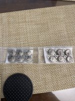
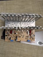
The heat sinks are separate. There's one for each channel each holds six mosfets 3 n channel and 3 p channelsThe schematic shows no source resistors so it can do without TO3 insulators. However the two heat-sink's should not connect to each other.
Have you checked that?
Attachments

This is about the left and right channel that should not touch, not the positive and negative halves.
If there is any question about heatsinks just get some insulators and install them. You're wasting time fretting over it when you could just take care of the concern once and for all.
Look, I've been doing this stuff for more than half of a century. Do you want to get to the bottom of this or not?
Look, I've been doing this stuff for more than half of a century. Do you want to get to the bottom of this or not?
No they don't touch. Is there any way to check the driver board now that the mosfets are out with the power on?Yes, but on the picture they are very close together, and I cant see if they touch or not.
Maybe if you can find some other way to close the feedback loop without creating an oscillator. Do you know how to do that?Is there any way to check the driver bored now that the mosfets are out with the power on?
There might be some other way too, but it would likely be very touchy with the feedback loop open. That's because there is a lot of open loop gain. Of course one could change that by modifying the circuit, but is that likely to be the best approach at this point?
EDIT: Why the hesitancy? You seem to have no idea of what to do at this point. There is another tact you could take. Is it that you don't want to do the work to reassemble the thing?
Its like this, sometimes troubleshooting requires localizing the problem area. Sometimes there is not a one-step, direct route to easily finding the problem. Imagine a big system that is spread out over multiple rooms full of equipment. Do you think you open everything up, take everything apart and try to find the problem with only a DVM and your eyeballs? Probably not, unless maybe you already have a pretty good idea from experience on exactly where you need to look and for what. Sometimes you have to use other tactics, is all.
Last edited:
Use 2pcs of identical 2k2-10k resistor, 1 soldered between gs of n channel, the other between gs of p channel.No they don't touch. Is there any way to check the driver board now that the mosfets are out with the power on?
I have spent years with these Mosfet amps. I always repair and check the whole cirquit without the Mosfets installed. This is no problem and you only can blow cheap parts. When you see a clean signal at all gate resistors, you should be done and solder in the Mosfets as a last step. So leave them out by now.
I'm quite sure you have a very simple fault. The way to find it is to have both channels installed and powered (except Mosfets) and compare voltages left to right, left to right and so on... Print out the schematic and mark every point where voltages differ at the defective side. You can not miss the fault this way, simply impossible. Don't think and speculate, check!
I had a look at your PCB pictures, there is a region where things get ugly, because traces are too narrow to tell them apart. Exposed copper can grow out over time and make a tiny connections. A brass wire brush is a great tool!
Also some solder points look bad. I put it on your little experience, but it is just 5 seconds to touch them up when you look at the PCB. Don't leave that to "I do it later".
PS use something to magnify the traces, a lot of light and a high resolution camera help. You will see how relaxed x10-20 is compared to staring at the area 1:1.
Last edited:
The reason I sent that message to Indra was to know if the test required mosfets in or mosfets out. Not because im too lazy to dig in. I've been working on this thing every free minute I got.Maybe if you can find some other way to close the feedback loop without creating an oscillator. Do you know how to do that?
There might be some other way too, but it would likely be very touchy with the feedback loop open. That's because there is a lot of open loop gain. Of course one could change that by modifying the circuit, but is that likely to be the best approach at this point?
EDIT: Why the hesitancy? You seem to have no idea of what to do at this point. There is another tact you could take. Is it that you don't want to do the work to reassemble the thing?
Its like this, sometimes troubleshooting requires localizing the problem area. Sometimes there is not a one-step, direct route to easily finding the problem. Imagine a big system that is spread out over multiple rooms full of equipment. Do you think you open everything up, take everything apart and try to find the problem with only a DVM and your eyeballs? Probably not, unless maybe you already have a pretty good idea from experience on exactly where you need to look and for what. Sometimes you have to use other tactics, is all.
I have spent years with these Mosfet amps. I always repair and check the whole cirquit without the Mosfets installed. This is no problem and you only can blow cheap parts. When you see a clean signal at all gate resistors, you should be done and solder in the Mosfets as a last step. So leave them out by now.
I'm quite sure you have a very simple fault. The way to find it is to have both channels installed and powered (except Mosfets) and compare voltages left to right, left to right and so on... Print out the schematic and mark every point where voltages differ at the defective side. You can not miss the fault this way, simply impossible. Don't think and speculate, check!
I had a look at your PCB pictures, there is a region where things get ugly, because traces are too narrow to tell them apart. Exposed copper can grow out over time and make a tiny connections.
Also some solder points look bad. I put it on your little experience, but it is just 5 seconds to touch them up when you look at the PCB. Don't leave that to "I do it later".
PS use something to magnify the traces, a lot of light and a high resolution camera help. You will see how relaxed x10-20 is compared to staring at the area
That's what I'd do to test voltages with mosfets not installed.Indra. You know that my mosfets are not installed right?
- Home
- Amplifiers
- Solid State
- can anyone offer help understanding the flow of this circuit