Now the wires are shortened to the shortest possible. However the oscillation is even worse, now the measured ripple is almost 5Vpp at 500KHz. Sorry about the incorrect statement at post1#. It should be 500KHz not 10MHz.
Go ahead and listen to the amp; inclusive its oscillation. Please report your observations. You will eventually cure the oscillation. and compare both experiences.
I had a curious experience with an oscillating diyamp. Didn't know it; and it sounded superb; until I remedied the oscillation.
I had a curious experience with an oscillating diyamp. Didn't know it; and it sounded superb; until I remedied the oscillation.
Go ahead and listen to the amp; inclusive its oscillation. Please report your observations. You will eventually cure the oscillation. and compare both experiences.
I had a curious experience with an oscillating diyamp. Didn't know it; and it sounded superb; until I remedied the oscillation.
Thanks Antoinel. That is a good idea. 😀 That was what I did. the sound was not bad, until I found the oscillation. Now it was not very pleasant to listen to an amp with oscillation. 😡
Interesting thing is no mater how I adjust the amp, the oscillation only appears at the negative half. Any hint?
I think the negative half cycle quasi-comp circuit has too much gain. Try putting a 47R resistor in the emitter of Q4, and perhaps a 100pF cap across the base and collector of Q4.
I think the negative half cycle quasi-comp circuit has too much gain. Try putting a 47R resistor in the emitter of Q4, and perhaps a 100pF cap across the base and collector of Q4.
ihan, Thank you very much! I believe that there will be some true expert to give me a hand. Here you are. That is what I did tonight, replaced the B649 with an lower hfe one, and it fixed the problem completely! and now the amp has 10x gain at 1MHz without a sign of oscillation. Also the 5Hz square wave is much clean and smooth. I will post some photo by tomorrow. So tired and want gogo sleep.
Thanks Antoinel. That is a good idea. 😀 That was what I did. the sound was not bad, until I found the oscillation. Now it was not very pleasant to listen to an amp with oscillation. 😡
Interesting thing is no mater how I adjust the amp, the oscillation only appears at the negative half. Any hint?
Aah the power of our minds. Hope you could investigate the following.
- Disable the 2 feedback loops. Determine open loop gain, stability of quiescent points, oscillation etc.
- What is the closed loop gain of the amp. I am thinking the upper half is equal to 20 and ditto for the lower half. But; is the net closed loop gain 20 or 10?. Suppose it is 10, then it is inviting an expected oscillation .
- Increase close loop gain.
- May even consider a closed loop gain for the upper circuit that is different from its lower half [within reason]. Akin to the earlier recommedation by ihan.
- Can the circuit accept one central negative feedback loop instead of two?
Dont remember exactly the condition when amp become an oscillator but it something like where your phaze shift is 180 the gain must be a bit more than 1. So, if you drop your gain below 1 where it gives you 180 degree the problem has to go. And I dont think that you need such a super flat gain till 3 MHz since any human being is capable to recognize sound waves only below 16 kHz, ( some individual Who never drunk or smoke or listen Nirvana very loud can recognize up to 18 kHz ) So, whatever is above is not really necessary. Make it flat till 100kHz the rest is radio span =)
10MHz would be the range to expect from an oscillating mosfet. 500KHz is probably related to the poor phase margin. Try placing compensation across R5 & 6.
Problem fixed, Lower hfe 2SB649 is the cure
Hello all,
Thank you very much for your help, comments, and/or attention. Your ideas certainly contributed to the development of this quasi-symetrical design. I have asked Lazy Cat to help developing his very simple symetrical amp ie. VSSA to use only N-mosfet for o/p. But he gentally refused due to thermal stability and performance considerations. I understand that I need put more in thermal compensation to make the quasi o/p as stable as LC's VSSA, and I think it is achievable. I also think the quasi mosfet o/p is the most doable o/p mode that will continue gain favour from diyers, given the status that V N-Channel mosfet is much more widely used and much cheaper than P-Channel, and cheaper than lateral fets. Quasi o/p also allows easier and better match of the output transistors. I think LC does not want to put more transistors in his VSSA because he promised that he should keep the amp design 6 transistor only. Not wanting to spoil LC's threads, I initialled this new ask-for-help thread. Neverthless, I regard LC's symetrical amp design is smart and tremendously informative. If you are going to build some current f/b symetrical amp, you can put LC's designs on top of your wish list.
Problem fixed, Lower hfe 2SB649 is the cure
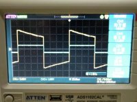
As I have wrote previously, the problem has been fixed with a low hfe B649AC as the lower half driver transistor. The amp has a gain close to 20x, it maintains the gain 10x at 1MHz.
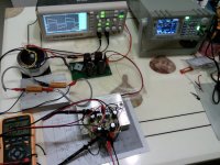
Attached are the photos.
Set up
Low Freq Square Wave
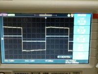
High Freq Square Wave
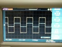
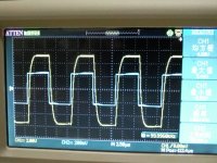
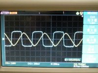
As I have wrote previously, the problem has been fixed with a low hfe B649AC as the lower half driver transistor. The amp has a gain close to 20x, it maintains the gain 10x at 1MHz.
Attached are the photos.
Set up

Low Freq Square Wave


High Freq Square Wave


How's it sound without the annoying oscillation?All the tests were performed with 4Ohm resistive load.
hehe, I am listening to it. I should say that has a deeper base compared to my NAP140 clone. for the high side, I feel it brings a lot more details out from the music. The middle is comparable to my JLH 1969 Class A, but the JLH sounds a bit sweeter.
With out thermal compensation, the current stables at about 490mA. I am using one amp to drive two speakers = 4ohm.
With out thermal compensation, the current stables at about 490mA. I am using one amp to drive two speakers = 4ohm.
Hi jazzclassic 
Glad that you've solved quasi complementary VSSA to operate oscillations free. As it was suggested Q4 would need emitter resistor as local feedback same as Q3. In that case you could leave higher hFE Q4 in operation.
Also C3, C5 compensation only is not the best solution soundwise speaking. C3, C5 should be lowered to app. 5 pF and at the same time 20-50 pF capacitor should be added from each collector of Q17, Q18 to GND. That's the way to get lowest HF distortions possible from this design.
Another thing for sound improvement is to change R2, R3 with j-fet adjustable current sources. Also R4, R7 should be 100 ohm or less, depends on max OLG and still closed loop stable, now OLG is just to low.
OK, please check and report. I just wish you to squeeze out max sound quality from VSSA design as possible, it deserves to be treated that way. 😉
Hi jazzclassic
Glad that you've solved quasi complementary VSSA to operate oscillations free. As it was suggested Q4 would need emitter resistor as local feedback same as Q3. In that case you could leave higher hFE Q4 in operation.
Also C3, C5 compensation only is not the best solution soundwise speaking. C3, C5 should be lowered to app. 5 pF and at the same time 20-50 pF capacitor should be added from each collector of Q17, Q18 to GND. That's the way to get lowest HF distortions possible from this design.
Another thing for sound improvement is to change R2, R3 with j-fet adjustable current sources. Also R4, R7 should be 100 ohm or less, depends on max OLG and still closed loop stable, now OLG is just to low.
OK, please check and report. I just wish you to squeeze out max sound quality from VSSA design as possible, it deserves to be treated that way. 😉
Hi LC,
Thank you very much for the above suggestions.😀 I am doing the simulation in the Spice. The distortion is lowered to -76db from about -66db. However if lower R4 and R7 to 100ohm, the current through Q17 and Q18 would be increased to 12.6mA. should I use more powerful transistors here?
Hi LC,
Thank you very much for the above suggestions.😀 I am doing the simulation in the Spice. The distortion is lowered to -76db from about -66db. However if lower R4 and R7 to 100ohm, the current through Q17 and Q18 would be increased to 12.6mA. should I use more powerful transistors here?
Lower R44, R45 to 470 ohm, normally Q17, Q18 should have 10-12mA bias so here's the right place for KSA1381/KSC3503 or similar transistors.
Use j-fet current sources instead R2, R3. 😉
- Status
- Not open for further replies.
- Home
- Amplifiers
- Solid State
- Can anybody help me? This amp oscillate at 10MHz?