Several amplifiers, working together this transformer result unstable...and this hell thing made me change a lot of things in my amplifier to face interferences i believe this one have generated.
The interferences, oscilations superimposed, have appeared in several amplifiers...even in the Destroyer Amplifier, the Standard and first one...i had in other amplifiers also, as Aksa 55, Symassym and DHR Turbo.
So, this explains the reason why folks had not troubles with their amplifiers...the main trouble was in my home...not inside their homes...they use to say the Dx Blame ES works fine and stable.
Maybe the transformer is the problem...removed, even the Dx Blame ES, the former one, had worked fine.
I would like to ask someone to explain me these things..if Toroidal transformers can do that, and also if you think i have a bad solder inside...or if i need to shield ...well..this is the first Toroidal transformer i have..... this is something very new to me....i tried several types of filters...but the transformer was the cause.
Maybe the entire Dx Blame ES unstability was because of this damned one!
regards,
Carlos
Attachments
Typical values I measure are about 150pF for EI transformer and 1nF for a toroidal transformer 300VA.
However, I do not experience interferences, oscillations etc.
However, I do not experience interferences, oscillations etc.
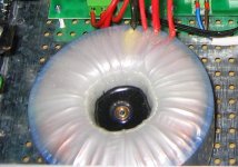
I have dismounted to check the transformer and then i assemble it once again
I found anything strange on it.....i have to search for magnetic fields and to find a way to measure the inductance to calculate if i have a tuned circuit....say,... ressonance.
regards,
Carlos
I found anything strange on it.....i have to search for magnetic fields and to find a way to measure the inductance to calculate if i have a tuned circuit....say,... ressonance.
regards,
Carlos
Attachments
If you scope the secondaries can you see anything odd... toroidals "pass" mains borne rubbish more easily than EI types.
Very odd... as you know the PSU should have such low impedance (all the caps) that the transformer shouldn't cause a problem.
How "big" is the oscillations you are getting. Very odd indeed. The amp should be immune to such things... but you say it happens on many with this toroid.
Very odd... as you know the PSU should have such low impedance (all the caps) that the transformer shouldn't cause a problem.
How "big" is the oscillations you are getting. Very odd indeed. The amp should be immune to such things... but you say it happens on many with this toroid.
While I have difficulties to understand the exact appearance of the symptoms you're mentioning (what about a scope photo..?) I'd guess that they might be reduced by a proper snubber network for the rectifier. See www.hagtech.com/pdf/snubber.pdf
Samuel
Samuel
I strongly suspect bad wiring practices such lack of star earthing, "ground bounce" due to shared return impedance etc rather than any transformer.....
I never had a problem with such a transformer..
Could it be that it s a faked one with a fake, or very
bad quality core, with very poor magnetic permeability?..
It makes me wonder, since fake electric components is
now a common practice.
Could it be that it s a faked one with a fake, or very
bad quality core, with very poor magnetic permeability?..
It makes me wonder, since fake electric components is
now a common practice.
I will post images...i was avoiding not to spread terror about my amplifier
I have dismounted and re assembled the transformer once again, i have cutted wires and i have soldered new output wires..... so....latter i will try the monster one once again... then, i will make pictures..now i can show...as i found the guilty.
It is interesting...i am sorry very much...but i am sure, because tests made..the transformer was the problem (before i have dismounted and mounted it once again).
I have made audio explaining what happened and sent to 47 friends..if you want the audio inform you personnal adress..it is in English and then in Portuguese.
regards,
Carlos
No, i friend made it, he has the machine to do that.
I have dismounted partially, cutted all connections and made it once again..trying to find something strange..bad solder junction, wire insulation broken...wires loosen.... i have found anything strange.
I think we can made it by ourselves..but too much hard work..this one was not made by me..the guy is a professional, he is the one fix and construct customized transformers in my town..he is also representative of several audio factories we have in Brazil, and all them uses this kind of transformer..he is the boss, the Shop owner, but as he is personnal friend, he coiled this one with his own hands.
I have not tested after i have ressoldered..also have not tested the transformer outside the case...i have tried that transformer ground in the enclosure (center tap, secondary coil winding) and without that ground..also i have insulated the one with clothes..so, no electrical conduction to the chassis...maybe magnetic field...i have to run wires and install the one distant from the amplifier to see what happens.
Interesting...the trouble i had..the oscilations, the blurring in the scope image, the other image superimposed that look alike Television Waveform monitor... a very big image...multiple lines..only happened when i was injecting high amplitude of square waves with 10 kilohertz or upper that frequency...only this way.... small superimposed oscilations happened too because the feedback condenser, the one Krachkiste suggested me to remove..also the waveform the slew rate was a little bit better without that feedback capacitor.
The amplifier is rock stable now...you can do whatever you want..to force it the way you want (respecting output transistors power dissipation naturally) and it is stable..rock stable..perfect!
I do not know what happened...till this moment i have troubles to accept that..very strange..but happened, it is truth..was tested with two standard transformers....the toroidal returned to work and presented once again..... i have removed all my supply filters and snubbers and coils..also i have tried another filter, also i have tried another rectifier..a discrete one... assembled the 4 diodes.... and only the transformer replacement fixed...the gray transformer used has 10 percent lower voltage..the black one has 10 percent higher voltage.
regards,
Carlos
Last edited:
Looks like a saturation of the magnetic core..
The voltage would collapse at high currents ,
but the supply capacitors should make this impossible.
Anyway, a bizarre beast this transfo...
The voltage would collapse at high currents ,
but the supply capacitors should make this impossible.
Anyway, a bizarre beast this transfo...
Bizarre..no doubts...maybe it was not very well constructed
I do not know about how many turns were used....also i do not know about the core quality...i hope it is fine.
I will try it distant..also i will move it using my hands and will be almost floating over the board, almost touching...i want to see if this is magnetic field or not.
I have tried to disconnect the secondary center tap from ground.... also i have installed and tested too...also i have tried to insulate the one from the chassis using a piece of wood...but magnetic decoupling i could not make as it was near the iron enclosure..i will try, latter, or tomorrow (my daugther is visiting me) to see it very distant magnetically.
Maybe, the unit created toubles with the Dx amplifier too..and the Dx amplifier was inside another enclosure..so..distant from magnetic fields.
This is very confused to me.
regards,
Carlos
one thing that can happen with a toroidal transformeris the mounting bolt becoming a shorted turn if it is in electrical contact with the top and bottom of the case. it can also couple induced voltages to the top and bottom of the case if the mounting bolt isn't isolated from both top and bottom of the case. a lot of manufacturers use a steel can around the transformer to isolate it from the rest of the amp.
Unclejed - if that happened you'd know about it REAL FAST! It's like picking up a hot soldering iron by the wrong end.
I suspect bad wiring practices were made 'worse' with the 'better' trafo. If you build each 'channel' on separate boards you really have to be careful how you ground everything. It may not even be possible to get an optimum solution that doesn't break one of Self's rules, somewhere.
I suspect bad wiring practices were made 'worse' with the 'better' trafo. If you build each 'channel' on separate boards you really have to be careful how you ground everything. It may not even be possible to get an optimum solution that doesn't break one of Self's rules, somewhere.
Transformers and wiring with a particular set of parasitics can trigger amplifier instabilities only if they actually exist in the circuit.
Replacing the transformer is just trying to hide the problem rather than solving it.
Replacing the transformer is just trying to hide the problem rather than solving it.
The transformer and parasitics are part of the 'circuit'. It's common practice to stabilize RF and microwave power amplifiers by putting a garbage-grade low Q bypass capacitor just outside the package. The same kind of capacitors that audiophiles cringe at the mere mention of.
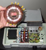
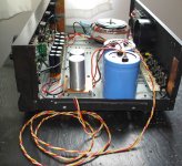
I will show you what i have made..testing the transformer once again.
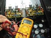
It was dismounted (partially) to cut connections and to solder them once again, to inspect to see if i have loosen wires, or wires with insulation damaged, shorts or strange things inside...nothing found...
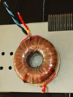
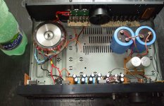
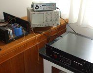
them i assemble in the chassis you see in the second picture...in the first picture i was testing the high voltage winding and them i changed to the correct one, that produces 39 volts. (picture 3).
regards,
Carlos
It was dismounted (partially) to cut connections and to solder them once again, to inspect to see if i have loosen wires, or wires with insulation damaged, shorts or strange things inside...nothing found...
them i assemble in the chassis you see in the second picture...in the first picture i was testing the high voltage winding and them i changed to the correct one, that produces 39 volts. (picture 3).
regards,
Carlos
Attachments
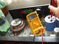
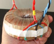
You see in the first picture, i have installed a long cable
It is twisted, but this produces small capacitances, and some inductances too.... the real thing had not long cables and not twisted cables and created troubles even without the long cables.
The i have installed these cables, new rectifier and other filters, other enclosure, distant 1 meter from the amplifier under test.
regards,
Carlos
Attachments
- Status
- Not open for further replies.
- Home
- Amplifiers
- Solid State
- Can a toroidal transformer produce all this mess?