The one starts with a 0.7 milliohms reading that climbs slowly (got to about 1.2mOhm after a couple of minutes and was still climbing). The other starts at 7 milliohms and falls steadily. Is that bad?
You can't check leakage this way.Check the capacitors are not leaky by measuring on the ohms range. they should eventually read infinity if given long enough to charge. If they are not leaky it is safe to put them back in.
Despite Allen saying you can't check capacitor leakiness this way, a good capacitor will read infinity ohms on a typical multimeter.The one starts with a 0.7 milliohms reading that climbs slowly (got to about 1.2mOhm after a couple of minutes and was still climbing). The other starts at 7 milliohms and falls steadily. Is that bad?
Just for fun I tested two Nichicon Muse bipolar 100µF caps. Starting from almost a short circuit (very low ohms) they both took less than five seconds to read off the Ω scale of two of my multimeters, which is >100MΩ (100 megohm or 100,000,000Ω).
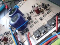
Your capacitors are faulty if they will not read off-scale on the Ω range. However I am more concerned about the state of soldering where I highlighted it. Some of the joints looks suspect in the low resolution image.
And after that you can switch to ohms reading and see them
discharge slowly down from 2 volts (on a typical multimeter).
If the voltage decreases rapidly, the cap may be leaky or of low
capacitance.
discharge slowly down from 2 volts (on a typical multimeter).
If the voltage decreases rapidly, the cap may be leaky or of low
capacitance.
Ah, those readings I took were likely megaohms too. I took "m Ohm" as milliohms so stand corrected. I think the poor picture makes those joints look worse than others but have redone them in any case and an assortment of others.
It's back together and working just now, but it was for a while when I started on it this morning so don't take much from that. Probing and flexing the board and components showed up nothing and I ended up putting the old red caps back in. I'll wait and see and will report back but will order replacement 220uf caps anyway.
Thanks for the suggestions.
The problem is back but slightly altered. There's always been a switch on power "thump" with this amp and that seems to be the start point for this issue. Right now it (the driver being pushed forward and sitting there buzzing) starts at the thump but clears after a couple of seconds. I am giving up for now but will try the new caps if they are easy to get.
Thanks all.
Thanks all.
Last edited:
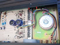
Once you checked the soldering I was starting to wonder if there is a problem with one of the windings on the transformer. Then I found this thread:
[url=https://www.vintage-radio.net/forum/showthread.php?t=142155]Cambridge P40 Amplifier - UK Vintage Radio Repair and Restoration Discussion Forum[/URL]
I think you may need a new transformer. 2 x 18 Vac @ 2 Amp will do just fine. Something like this: Vigortronix VTX-146-080-218 Toroidal Transformer 80VA 0-18V | eBay
Check that both + and - rails are present when you have the fault, they should be around 28Vdc. Then check you have 18Vac on both of the transformer secondaries; one gives the + rail and the other the - rail. If one is missing, the transformer is faulty. It seems that is not unheard of with this model.
Last edited:
Crikey, you couldn't get a better match for the problem than that. Cheers johnmath, I'll get a transformer and caps ordered.
True, a failing capacitor can pass the ohm meter test. However a capacitor taken out of service that fails the ohm meter test is leaky.In addition an electrolytic won't always show increased leakage current when it is failing.
That still doesn't necessarily mean capacitor leakage is the cause of the problem in this case. A fault that manifests identically in both channels at the same time likely has a common factor, i.e. power supply.
Just looked at the transformer in there and it's an:
Airlink Transformers 0279-724425 P40
I can't see much about it, but one page suggests it is (235v) 2x32v and the other (using 235v but mentions it's a 220v version) measured 2x32v.
Not sure what to order now.
Airlink Transformers 0279-724425 P40
I can't see much about it, but one page suggests it is (235v) 2x32v and the other (using 235v but mentions it's a 220v version) measured 2x32v.
Not sure what to order now.
Last edited:
I can't find literature on the MkII version of the P40. Do you have an owner's manual? If so post the rated power output specifications at different loads.
I assumed the technician in the thread linked was correct when he said 2 x 18Vac windings, which gives rails about ±28-30 volts at idle. Check the AC voltage from the each of the windings on your transformer, and also measure the DC rail voltages across the large capacitors, and post back here. I suspect the reference you found to 2 x 32 is an error, and it should have been 2 x 16 (32V overall).
Alternatively why not email Airlink with the original part number and ask their recommendation for a replacement? They would either have a stock unit close enough or can wind an exact replacement for you.
Toroidal Transformer Range | Airlink Transformers
There is a P40 listed for parts here:
Cambridge Audio P40 Amplifier with MM/MC Phono Stage SPARES REPAIRS POWERS ON | eBay
Last edited:
Unfortunately I've found little info on this amp over the years and have no manual. I'll measure as you suggest and have emailed Airlink too. Many thanks.
Also measure the outside diameter and height of the toroidal transformer because those dimensions will give the VA rating of the original.
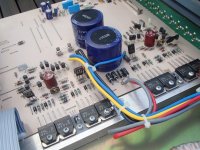
The reason I pointed out those ROE caps is because they are a known problem in other amplifiers, for example Cyrus 1/2 amplifiers have these and they go bad there, causing similar faults.
Ideally the capacitor should be bipolar, but in reality they will barely see any reverse voltage across them so regular polarised electrolytics will work fine. Put it this way - most other amplifiers of similar topology have normal capacitors there!
It may be worth checking the power rails are both present, but I would be skeptical if thats the fault. If it is, I'd probably replace the 1N5408 rectifier diodes with a 16A bridge mounted to the case.
If the transformer needs replacing, the VA rating is given on the back of the case as 180VA. With two pairs of outputs per channel, I'd be inclined to believe 2x25VAC would be suitable, though the amp is apparently only rated for 40W into 8 ohms. It wont really matter too much if the voltage is lower - you'll just get less output power, but the amp should otherwise work
I'm not able to strip the amp right now but the red and grey cables running onto the board from the transformer each show 29v AC (off a 220v supply).
The transformer is 3.5cm high (4.5cm including height of the shoulders), 8.7cm diameter with a 3.5cm hole in the doughnut.
It's good to know I don't need to match the transformer too precisely.
The transformer is 3.5cm high (4.5cm including height of the shoulders), 8.7cm diameter with a 3.5cm hole in the doughnut.
It's good to know I don't need to match the transformer too precisely.
Attachments
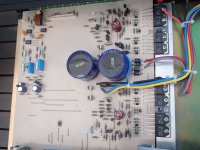
That's 29vac each one with respect to ground (chassis), which would mean 58Vac between red & grey?
That means the rated secondaries would be rated at ~25Vac each, which would give ±35Vdc rails.
The dimensions would make it an 80VA transformer. I think it is this one:
Airlink Transformers
That means the rated secondaries would be rated at ~25Vac each, which would give ±35Vdc rails.
The dimensions would make it an 80VA transformer. I think it is this one:
Airlink Transformers
- Home
- Amplifiers
- Solid State
- Cambridge P40 (MkII) in need of help