Ian, The Cambridge A500 I'm working on has an obviously factory fitted mains earth
via a wire from the earth pin of the IEC mains socket to the metalwork(chassis)of the amplifier. What was never fitted was the connection from the 'chassis ground' side of R267/C210 to chassis, so these two components were left 'floating' from new. I may well leave it that way when I reassemble the amp. For the moment my added 'earth' connection is simply a convenient way of connecting my DMM so that I can easily measure the +ve & -ve DC voltages. Admittedly the circuit diagrams do not show a mains earth, but I can assure you that one is present, as I stated above. I'm not sure what you mean by 'designs for DIY purposes have to be a no-no according to forum rules. This is DIY Audio after all!
via a wire from the earth pin of the IEC mains socket to the metalwork(chassis)of the amplifier. What was never fitted was the connection from the 'chassis ground' side of R267/C210 to chassis, so these two components were left 'floating' from new. I may well leave it that way when I reassemble the amp. For the moment my added 'earth' connection is simply a convenient way of connecting my DMM so that I can easily measure the +ve & -ve DC voltages. Admittedly the circuit diagrams do not show a mains earth, but I can assure you that one is present, as I stated above. I'm not sure what you mean by 'designs for DIY purposes have to be a no-no according to forum rules. This is DIY Audio after all!
Last edited:
Thanks for the exlanation, OXAUDIO. 'Good that it is a mains earthed assembly, since it permits relatively safety. If a design is double insulated, it requires an isolation transformer in the line to render the device safer for people to work on. TVs once used used highly dangerous neutral connected chassis designs which also had to be isolated for safety.
DIYaudio does not support suggestions to alter designs affecting mains safety, nor non-isolated switchmode power supplies and sometimes, double insulated wiring. Check the rules. Portable appliances such as audio amplifiers may also be subject to national and often internatonal regulation, whether it is DIY activity, Professional or Industry regulations and surely that's relavant to 12 year olds etc. reading this forum and subsequently, innocently playing with live mains power devices which, though functional, could still be decidedly unsafe when opened.
I would understand that for members posting here, it is a matter of avoiding perceptions that we ignore or encourage disregard for safety regulations. What we individually risk beyond this, hopefully will remain our own private affair - as long as we still live, that is. 🙄
No connection from Main Audio Ground to Chassis.
Check the resistance from Main Audio Ground to Chassis on both the resistance scale and the diode scale.
Check the resistance from Main Audio Ground to Chassis on both the resistance scale and the diode scale.
Andrew, as i noted earlier, the main '0v' line is not connected to chassis. The 'chassis ground'(their description) end of R267/C210 was never fitted. I may probably leave it that way. In the meantime I've done some further tests using a lower voltage supply. The o/p transistors are OK, but I am replacing the 8 x 2200uf main smoothing capacitors as a precaution, so hopefully will have the amplifier up and running again soon!
Have you measured it?........
Check the resistance from Main Audio Ground to Chassis on both the resistance scale and the diode scale.
Before I first opened up the A500, Andrew, I thought it odd that the speaker negatives were isolated from the chassis. When I looked/checked inside, as I mentioned in an earlier post, I found that the DC '0v' rail, to which the speaker 'grounds', TX secondary center tap, et al, are connected, is isolated from the chassis because the 'ground lift' components(R267/C210) had never been earthed from new.*
In the meantime, I have temporarily connected a transformer & rectifier assembly supplying -25/0/+25v DC to the power amplifier, which works fine. Next step is to run it from a higher voltage DC supply, but I'm beginning to think that the only fault all the time was the O/C primary of the original mains transformer. Anyone else care to comment on this?
* There is an earthed connection from the I/P sockets, etc., PCB, but, AFAIK, this doesn't earth the main amp. PCB even when all the pluggable interconnects are re-instated.
Last edited:
I wouldn't get flustered about the ground lift. The schematic shows it as normally disconnected also. That means the feature is optional so that it suits various local regulations. What you don't know is whether when the case is earthed, that the "ground lift" was ever intended to be a safe, necessary or satisfactory addition on your mains supply. So don't add to what was intended in accordance with the compliance sticker.
AFAIK, most Cambridge Audio product is for direct global distribution from China and previously elsewhere in S.E Asia. The boards have to suit every possible configuration from double insulated to earthed and unearthed mains supplies, with minimal factory changes for different markets. If you are unaware of other regulations than your local UK requirements that could just as easily be applied by unspecified factory mods to the same equipment for use elsewhere, don't tinker with what ain't broke.
The likelihood is that this is essentially a double insulated design, with only the amplifier case grounded and that helps shielding and avoiding the "tingles" sensitive folk get from touching such equipment. It is not safe for DIY construction though, which takes a belt and braces, all grounded form for obvious reasons.
So far, the only thing you have found wrong with the amplifier is evidently the transformer primary winding fuse which is where you started back in #9. If the amplifier works fine as you say, now that you have fitted a substitute transformer and diode bridge, is there any further need to delay replacing the original transformer as suggested? Unless you want to upgrade parts, it would seem it's soon time to close up and enjoy.
Last edited:
The amplifier is now working fine, based on a couple of hours listening to records being played through it. I have to admit that I wouldn't have spent so much time testing & checking for faults had it not been for information gleaned from this forum. I'd almost certainly simply have replaced the mains transformer, which, in the end, turned out to be the only fault.
Cambridge Audio A500-worth repairing?
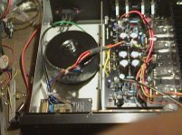
Following on from the above, here are a couple of photos taken after I had replaced the faulty mains transformer with an MCTA160/30(FF01567) 30-0-30v 160VA type from CPC. The green wire partly visible behind the transformer is the factory fitted mains earth. It goes to a nut & bolt screwed through the bottom panel.
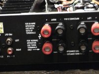
The instructions(apart from using 6 to 8 ohm speakers) on the rear panel seem to me to be irrelevant, since the two speaker connections provided for each channel are internally paralleled by the manufacturer. It therefore doesn't matter which pair are used if only two speakers are connected.
Following on from the above, here are a couple of photos taken after I had replaced the faulty mains transformer with an MCTA160/30(FF01567) 30-0-30v 160VA type from CPC. The green wire partly visible behind the transformer is the factory fitted mains earth. It goes to a nut & bolt screwed through the bottom panel.
The instructions(apart from using 6 to 8 ohm speakers) on the rear panel seem to me to be irrelevant, since the two speaker connections provided for each channel are internally paralleled by the manufacturer. It therefore doesn't matter which pair are used if only two speakers are connected.
Attachments
Last edited:
In another forum I have read that toroidal transformers may fail due to the higher inrush currents in them. Over a week after replacing the one in the A500, it is still working perfectly well. I switch it on and run it, playing vinyl albums via a BDS95 record deck and outboard preamp. every day for 1-2hours. No problem (so far!)
Its true that toroidals have large inrush currents but I've never heard of it being a cause of failure. Remember a transformer is only "wire" and that is never going to fail due to a short duration inrush current. Same for heating effect, the duration is really tiny. The only failure mode due to inrush current would be either an unsuitable non replaceable fuse that fails or poor workmanship of some internal termination of wiring (windings) to the external leads/terminals etc.
Great its fixed by the way 🙂
Great its fixed by the way 🙂
The A500 is working fine now, albeit I never play it at really high volume, and only have two (6 ohm) speakers connected. It seems to me that it's a good amplifier, let down by perhaps an inadequate heatsink, although it lacks features such as A/B speaker switching, speaker switching relay, and even a headphone socket, all of which are present on most other amplifiers. They could no doubt be added to the A500 without too much difficulty.
You could add a speaker delay and DC detect circuit controlling a relay (mechanical or Solid State).
They do not take up much space and there are quite a few projects on this Forum that are suitable.
They do not take up much space and there are quite a few projects on this Forum that are suitable.
Mooly, they do have a thermal fuse in them. I've seen that fail simply because the whole case has gotten so hot due to the lousy heatsinking. The lack of DC protection is also unforgiveable - no direct coupled amp for domestic use should skip this!
It's a shame really as otherwise the A500 is a fairly nice amp - just too many corners were cut
It's a shame really as otherwise the A500 is a fairly nice amp - just too many corners were cut
Hi Jaycee, yes oc thermal fuses are a common failure in many products although I never normally associate them with large toroids. Inrush current shouldn't blow it though as they are temperature rather than current operated... is that what I said 🙂
These are the general sorts of thermal cut-out device tucked into the windings of toroidal and E-I mains transformers. You often see (or maybe saw) this basic type in domestic appliances like vacuum cleaners, fan heaters, kitchen aids, hair dryers etc where I think they were much better employed. I added this because of the interesting construction diagram.
Many low voltage lighting transformers are fitted with them in order to meet building safety requirements. It's just a convenient way to provide an approved form of disaster protection - another clever bit of corner-cutting that is just once-only and a dashed nuisance if it takes out the most expensive component of the device when it fails for any other reason.
These can also nuisance-fail in normal operation within their marked operating limits. They are not all as good quality nor precise as the specs. suggest. The performance is heavily dependent on the actual fusible material used and the assembly precision which may not be what we expect and I've seen cheap import LV lighting transformers stacked up at recycling centres for just this reason. I wouldn't speculate on failure mode but the flat types used in trafos are usually only offered in broad categories like 130 degrees C which suggests a similarly broad, statistical range rather than the narrow specs shown for premium grades.
IOW, as Mooly says, they could be unsuitable but I'd go further on this quality issue if the auto-censor permitted. 😉
Last edited:
- Status
- Not open for further replies.
- Home
- Amplifiers
- Solid State
- Cambridge Audio A500 - Worth Repairing ?