that is no excuse worthy of a DIYer.Don't have a variac
Build and use the bulb tester that is referred to regularly on this Forum.
Going to give this amp a rest...
Till I'm back home in Swindon in a couple of weeks.
I'm on holiday and the temp outside is over 35Celcius since last week .
.
Going for something cold with my mates...
Thanks everybody
Ric
Till I'm back home in Swindon in a couple of weeks.
I'm on holiday and the temp outside is over 35Celcius since last week
.Going for something cold with my mates...
Thanks everybody
Ric
Back for a update...
Amplifier up and running
But one question, is it normal for the Q8/118 and Q10/110 to get hot (very hot) they are now about 15mm from the board.
It is running fine for the last 3 hours but I will keep my fingers crossed.
By the way the problem were the LEDs.
They were brand new but for some reason they would not alow the amp to work (they lit up) replaced them with other ones and it worked first time.
Thanks
Ric
It is normal that they run hot. The reason is because Alex designed the amp for a lower voltage than was used by Cambridge Audio, so the BC639/640 transistors are running "on the edge" of their power handling.
If you can get and fit some TO-92 heatsinks to them, I think that might be worthwhile. Something like this
If you can get and fit some TO-92 heatsinks to them, I think that might be worthwhile. Something like this
Good idea but they don't fit in the board.
Will try to get the MJE243/253 when I get back in the UK.
Will try to get the MJE243/253 when I get back in the UK.
Hi everyone,
I bought a A3i in earlier this week, in very very good condition and no worries technical report, not unhappy!
Do not touch!
I come to you guys to know what is the value of the bias and from which component it should be taken.
I'll take the time to enjoy the sound of this little "Creek" (Hull signed with Cambridge) because I had never heard this brand before and I'll try to find him loudspeakers which go well.
Regards.
Hi All,
I got an old trusty A3i and would like to upgrade it as what Alex has suggested. I have received the schematics from Alex but on some of the recomendation, he did not specifically indicate the rectifier diodes that need to be change. SO I am not sure which of the diodes should I changed. Here is the list of parts to buy based on his recomendation. Any feedback and recomendation would be appreciated before I order these parts online. If I have listed the wrong parts, please correct me ( for the resistor change, is the one with 5% tolerence good enough for Audio? 1% tolerence are hard to come by:
For both performance and reliability:
1) All 4 LEDs replaced with a high temperature type green or yellow colour, lifted at least 15 mm from the PCB.
( LED Standard – 3mm/5V – Green = 4 unit )
2) Q10 (BC639) replaced with MJE243.
3) Q8 (BC640) replaced with MJE253.
4) Q11 (BD139) replaced with MJE243, mounted on top of Q13 (under one of its screws).
5) Q12 (BD140) replaced with MJE253, mounted on top of Q14 (under one of its screws).
Q11 and Q12 connected to the PCB by wires (either twisted or a bit of a "computer" flat cable)
( MJE243 = 2 units / MJE253 = 2 units)
6) D210 and D211 replaced with 10 Ohm 1W resistors
( 10 Ohm 1W Tol: 5% = 2 units : 5% tolenence is ok?)
7) The idle current is set for 85-90 mA (approx. 40 mV between emitters of Q13 and Q14) after a warm-up.
8) Resistors R8, R16, R18 should be at least 1W power. If these are only 0.5W - they have to be replaced.
( R8 =2200 ohm 1W = 1 unit, R16/R18 = 3300 ohm 1W = 2 units . Both are with 5% tolerence. Is 5% tolerence ok?)
For performance only:
9) Power supply rectifier diodes replaced with 100V 10A Schottky and capacitors in parallel with these diodes removed.
Which of the diode do I need to replaces? There are so many diodes in the circuit with different values. I am not even sure which section are under Power Supply vs protection circuit.
10) Electrolytic capacitors replaced with better types. The most important are C216 and C217. I've used Panasonic FC there with good results.
( C216/C217 = Panasonic FC = PN EEUFCOJ471 = 2 units)
11) Protection supply rectifier diodes replaced with Shottky 1A 100V, with added 30 Ohm 0.5W resistor in series with each diode.
Which of the diode do I need to replaces? There are so many diodes in the circuit with different values. I am not even sure which section are under Power Supply vs protection circuit.
12) The input differential pair Q1/Q2 replaced with a matched gain pair of BC550 (B,C) - this will substantially reduce the output DC offset.
( BC550 = 2 units )
Total Parts needed
( LED Standard – 3mm/5V – Green = 4 unit )
( MJE243 = 2 units / MJE253 = 2 units)
( 10 Ohm 1W Tol: 5% = 2 units)
( R8 =2200 ohm 1W = 1 unit, R16/R18 = 3300 ohm 1W = 2 units)
( C216/C217 = Panasonic FC = PN EEUFCOJ471 = 2 units)
( BC550 = 2 units )
Hello,
I'm looking for full schematics to my a3i which unfortunately died few days ago. If anyone could help I would really appreciate it.
My mail is: soroka at ua dot fm
thanks
I'm looking for full schematics to my a3i which unfortunately died few days ago. If anyone could help I would really appreciate it.
My mail is: soroka at ua dot fm
thanks
Just dug my A3i out of the loft ( a long time up there!), she works perfect, but what exactly is the reason for the 4 LED's??? It is bizarre! I used to know the reason but I have forgotten
OK its a budget amp and a hell of a lot less than what I am used to ( had a lend of an Audiolab 8000S for years and recently had to give it back), I'm using it for a computer amp and a pair of Tannoy Mercury M2's ( I'm not impresses but I have been spoilt over the years with grandeur)
OK its a budget amp and a hell of a lot less than what I am used to ( had a lend of an Audiolab 8000S for years and recently had to give it back), I'm using it for a computer amp and a pair of Tannoy Mercury M2's ( I'm not impresses but I have been spoilt over the years with grandeur)
LEDs have a constant voltage drop and are quite low noise, and cheap, so they are used as voltage references in current sources.
How do replace the Thermal Fuse within the Mains Transformer? Which Brand?
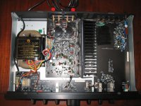
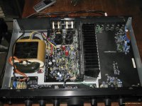
I have receive a death A3i. The reason therefore is a break thermal fuse (unfortunately not reversible version), fitted resp. mounted within the two coil bodies and the outer cladding for both coils of the R-core transformer. I short this fuse and introduce a new thermal fuse from Farnell close by the core:
G4A01117C - THERMODISC - FUSE, THERMAL W/E 117C | CPC
theory of operation from such fuses there is to read about
http://search.alkon.net/cgi-bin/pdf.pl?pdfname=03175.pdf
A heating of the transformer with the new ones can not be determined, even after more than 2 days non stop operating. Thus the reason for failured thermal fuse must be that fuse itself (unknown, why, but perhaps too weak for the associated inrush current - datasheet neither from the transformer nor from this genuine thermal fuse available by Cambridge Audio)
Now the Questions:
1) Which model/type is the genuine thermal fuse
2) How I remove the genuine thermal fuse?
3) From what brand, series and type number is this transformer (this transformer type isn't custom made version - only the inscription from the the outer cladding so as the wanted secondary voltage is custom made) ??
4) Where I can order a complete mains transformer device as replacement part?
The transformer brand/manufacturer could be one of the follow:
1) Foshan Nanhai Guicheng Dibao Electric
Foshan Nanhai Guicheng Dibao Electric Appliance Factory
2) Transcore Technologies
Transcore Technologies - R - Core Transformer, Torroidal Cores ( Round Cores ), R-Core 1 and 3 Phase for Transformers
3) Electro Assemblies Corporation
Mfg of toroid laminated ferrite transformers and r-core inductor coils
Basic informations regarding "R-Core"
R-Core
Thank you for your help.
Attachments
Last edited:
tiefbassuebertr ,
I have the transformer you are looking for in stock.
It is a dual primary for 120V/240V.
Let me know if you are interested.
Regards,
Michel
I have the transformer you are looking for in stock.
It is a dual primary for 120V/240V.
Let me know if you are interested.
Regards,
Michel
thank you for this advice. Please let me know the cost at whole (include the shipping costs from Quebec to Germany).tiefbassuebertr ,
I have the transformer you are looking for in stock.
It is a dual primary for 120V/240V.
Let me know if you are interested.
Regards,
Michel
My e-mail address:
kirschner-hifi@tiefbasswiedergabe.de
Dear tiefbassuebertr,
Bad news, I have been given the wrong information by my tech and the primary is 120V.
Really sorry for the false hope.
Is your transformer burned or is it only the thermal protection that is open?
I was looking at my transformer and it does not appear to be very difficult to replace, is it?
Best regards,
Michel
Are there no two 120 VAC windings?Dear tiefbassuebertr,
Bad news, I have been given the wrong information by my tech and the primary is 120V.
Really sorry for the false hope.
Is your transformer burned or is it only the thermal protection that is open?
I was looking at my transformer and it does not appear to be very difficult to replace, is it?
Best regards,
Michel
My transformer isn't burned as I already mentioned about post #152
I don't know, how difficult it is to replace the faulty thermal fuse (replace of completly transformer is very easy).
Therefore I want to introduce a second termal fuse inside of the transformer close by the secondary windings.
Last edited:
I have receive a death A3i. The reason therefore is a break thermal fuse (unfortunately not reversible version), fitted resp. mounted within the two coil bodies and the outer cladding for both coils of the R-core transformer. I short this fuse and introduce a new thermal fuse from Farnell close by the core:
I have 3 Cambridge Audio A3i and none of them have the thermal fuse in the tranformer and never had any problems.
As far I know you can run the amp without them as long you don't overdrive it.
Ric
Thank you for reply. Interesting to know. But are you sure? Have you found out this by open the insulation sleeving?I have 3 Cambridge Audio A3i and none of them have the thermal fuse in the tranformer and never had any problems.
As far I know you can run the amp without them as long you don't overdrive it.
Ric
On the insulating label from transformer version of my A3i device I read at the end
"115 °C THERMAL FUSE FITTED"
- go to the first picture by post #152
What is to read by your devices?
- Home
- Amplifiers
- Solid State
- Cambridge Audio A3i repairs and mods