wow... I have read this thread from start to finish, and I don't know if I am more confused than when I started...
Would someone be kind enough to make a concise summary as to what types/values of capacitors for what section, regulators etc for this player?
Cheers
Pete
In general....
My opinion is to stick to specified values, unless they are specced lower than the relevant i/c's dustsheet recommends. As for the types to choose its a good idea to look up the datasheets for the various i/c's to see what the chip manufacturer recommends.
More generally go for low very ESR types on digital supply rails such as Oscon SP or Oscon SPEC. These are widely regarded as the best. For annalogue supply rails take your pick! There ae many and each have a slightly different sound.
For ultimate detail maybe consider Rubycon ZL, ZLH, or ZA. For a more musical presentation consider Nichicon MUSE KZ - my current favorite.
Having said that, If I was to start over on my 640 I would probably concentrate on cleaning up the supplies first with upgraded regulators and some R/C or L/C filtering in strategic locations.
🙂
Nice and neat work there Mike, bet that player's sounding very good now.
Thanks again Lee 🙂
To sum it up it sounds more 'analogue' now. Detail is superb but not in a fatiguing way, in particular timbral detail is very much improved. Overall its a much more musical and enjoyable presentation with good PRaT. I find myself listening more to the music rather than analyzing the sound if you get what I mean. I'm very happy with it 🙂
I have some more mods planned but I think I'm getting into diminishing returns territory now. Plan to replace Ceramics around the opamps with Polystyrene's and maybe adding separate CRCRC supplies for analogue and digital rails. I might possibly go for even better regualtion soon with TeddyRegs.
This is all for later though as I need to finnish my dual mono Integrated amp first.
Good to hear from you 🙂
Here's a relevant thread on this machine over on pinkfishmedia.net:
powerin multiple opamps - cascaded rails or starred? - pink fish media
Watch this space 😉
powerin multiple opamps - cascaded rails or starred? - pink fish media
Watch this space 😉
Hi Guys,
i know this is a mammoth thread but I have a few question to ask in regard to actually repairing and modding my 640C V1.
My unit is 6 years old now, and after shipping it back from Australia to the UK, noticed a problem with the CD drawer going back and forth when trying to open and close the drawer.
When it did eventually decide to behave it's self, it sounded different although it has been some months since I last played it, but It sounded very harsh and unbalanced.
Upon closer inspection I found a number of leaked/leaking Electroclytics in the following areas.
Servo Board, C49 next to the heavily heatsunk voltage regulators, C82
Both 22000uF on the output board. adjacent to the 4 diodes forming the bridge rectifier.
I was think I may as well change these out for superior versions and change the NE5532P's for LM4562's.
I have also noted some hum from the transformer, the V1 does NOT contain a toroidal 🙁
Is it worth spending the money or should I look out for a second hand V2 to mod instead.
I notice the the bulk of this thread and attached images relate to V2 modding.
Attachments
if you´re buying 2nd hand you might look for a 740C , better sound , higher upsample , has toroidal transformer and you can still upgrade it.
Last edited:
The V2 is pretty much the same unit. It has an improved tx (needed for the extra circuits) and a twin dac output. The rest is the same.
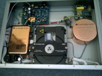
There is nothing wrong with a 'normal tx' they usually offer more current than the equivalent toroidal. CA used a copper plater can to cover the tx. Mostly for show but if you gnd it then is becomes a shield.
To be honest though, if you really want to upgrade it properly then you should add custom power supplies to isolate the circuits.
Brent
Thanks for the reply guys.
I guess firstly I need to have this unit in proper working order by replacing the electrolytic caps and then go from there.
Like 99% of people here I am on a limited budget, so I guess it is about getting bang for buck when it comes to modifying, and perhaps a progressive mod over a duration of time to spread out the cost.
Brent, What would you advise in term of upgrading power supplies, Spower or similar regs etc?
Kind Regards
Dom
Just an update to say I have managed to aquire a copy of the service manual for my V1. I would upload it here, however it is approx 4mb in size. If anyone would like a copy please drop me a line.
If there is anywhere I can upload this to for community wide access also please let me know.
Brent,
Would you advise earthing the shield/shroud over the Tx, I guess this could introduce RF noise into the circuit?
I am newbie to Audio as you can tell, although have some experience in other electronic disciplines.
Kind Regards
Dom
Hi Guys,
I have a question,
What would you advise replacing the two main smoothing caps on the main power supply? On version1 Schematic they are shown as C3, C24 22000uF 35V. I assume nothing too special as they are only smoothing caps.
I also plan to replace NE5532P's for LM4562's
Kid Regards
Dom
I have a question,
What would you advise replacing the two main smoothing caps on the main power supply? On version1 Schematic they are shown as C3, C24 22000uF 35V. I assume nothing too special as they are only smoothing caps.
I also plan to replace NE5532P's for LM4562's
Kid Regards
Dom
Hi Guys,
I have earthed to cover on top of the transformer as advised by Brent. Cheers Brent.
I have installed 8pin sockets where the op-amp are mounted so i can try a couple of different types of op-amp.
Iam also going to repalce the smoothing caps, x2 2200uF. for some Rubycon ones, they are not boutique but I am sure they are better quality over the stock ones which are branded 'NCD'.
I plan to add some damping to the case too.
Any hints and tip from your experiences are most welcome.
Kind Regards
Dom
Hi Andrew,
I made an error on a previous post and couldn't edit it, I must have left it too long before I realised.
I can confirm they are 2200uF 35V.
Cheers
Dom
I made an error on a previous post and couldn't edit it, I must have left it too long before I realised.
I can confirm they are 2200uF 35V.
Cheers
Dom
These are quite small. Where in the circuit are they located?
What size are the main smoothing capacitors?
What is the "normal" DC voltage across these capacitors?
What size are the main smoothing capacitors?
What is the "normal" DC voltage across these capacitors?
Hi Andrew,
From what I can tell these are the main smoothign caps for this part PCB, supplying the Voltage regulators that provide 15V to the op-amps.
The caps in question are lablled C24, C3.
Thanks
Dom
From what I can tell these are the main smoothign caps for this part PCB, supplying the Voltage regulators that provide 15V to the op-amps.
The caps in question are lablled C24, C3.
Thanks
Dom
Attachments

Last edited:
Hi,
Quickly simulated the circuit with shown below, and simply put a 1k resistor across the smoothing caps to act as a load.
You can see on the scope that with the 2200uF caps there is some ripple from them, I guess it depends how well the voltage regs respond to that ripple?
Dom
Quickly simulated the circuit with shown below, and simply put a 1k resistor across the smoothing caps to act as a load.
You can see on the scope that with the 2200uF caps there is some ripple from them, I guess it depends how well the voltage regs respond to that ripple?
Dom
Hi Andrew,
Those appear to be the main smoothing caps for the DAC board. The voltage appears to be stepped down by the transformer to 21v for this circuit.
I have replaced them with 2200uF 50V Panasonics. Just to see if it had an discirnable difference, it hasn't.
My System looks like this:
CDP: CA 640C V1
AMP: CA 640A V1
SPKR'S:ARCAYDIS AK3, FLOOR STANDING SPEAKERS, QED silver anniverssery speaker cable.
I find that the system sounds too bright and harsh. I was listening to 'The Reminder by Fiest' The vocals are very in your face and the guitar is very bright.
Overall I feel it is lacking warmth and I want a more natural subtle sound.
Kind Regards
Dom
Last edited:
- Status
- Not open for further replies.
- Home
- Source & Line
- Digital Source
- Cambridge Audio 640C v1 Mods