You describe exactly what I learnt chasing H2 distortion in my reference mono blockThing is with a class AB amp (which your amp is) the power supply takes half wave current. Think about a sine wave input. The + voltage supplies a current half cycle, then the - supply provides a half cycle current. So each supply provides current to the amplifier like an unsmoothed half wave rectifier - and that has a whole host of harmonics. That can easily couple into the input wiring, circuit board traces, and speaker wiring. Tightly twisting the wiring helps cut down the coupling of the current flow harmonics.
Thanks for the comments. I should probably just replace the caps and leave it alone...😆 but my sense of balance is talking to me very strongly. The "driver" (inverter) board is mounted all the way on the left, close to one of the transformers. The blue and yellow wires are the outputs from that board and route right past the transformer at close range. Then the right channel (this is a mono block, so not strictly right channel) cable goes all the way over to the right hand side. My sneaky plan is to make a nice pcb to replace the old one and place it right in between the two rectifiers (I would tidy up the ac cabling as well). That would make pretty close to equal runs of cable about half the original length. The input sockets are right in the middle at the back, so their cable length would halve as well and no longer go past the transformer. The MKT cap is soldered to the terminals just hanging in mid air so it could be mounted on the new board or left where is. The new board would be double sided with a ground plane, and of course ensuring the correct star type grounding with no current via audio return paths. Maybe I just have too much time on my hands... 😊
Oh, and there is already a ground loop with the current wiring back through the input cabling and the power ground cabling that shouldn't be there.
Hi Trackhappy,
Easy test. Just release the inverter PCB (the one on the side) and move it away to see if your supply noise decreases. That would answer that question pretty solidly. You could also simply pass some ferrous metal (a sheet) between the PCB and transformer. It isn't a driver board, just a phase inverter to bridge the two channels. That's its main function anyway.
Ground loops bad - as you know. Replace the connection to the power ground with a 100R resistor. That's as long as it isn't a current path.
What I've done is take some copper brake line and run the wires through that to the RCA input jacks from where ev er they need to go - depending on the amp. You can solder ground clips to that to secure it. Makes a really nice, neat solution. I have also used RG-174a wire (RF, used for test equipment) along with the copper tube (AKA brake line). I used brake line because it was cheap, and comes straight. Ever try and straighten tubing out so it is actually straight?
If the cap goes to the input RCA jacks, it is solid enough. This isn't airborne equipment, or mounted in a transport tractor (truck). Don't sweat things too much.
-Chris
Edit: - Oh, thanks for the picture. It will help me out.
Induced distortion is only an issue when you have layout issues. If you do, I doubt the rest of the amplifier is designed well (talking in a general sense).
Induced distortion is endemic in both commercial and home brew AB and B power amps, alas. Which is another reason that manufacturers quote distortion at 1kHz only.
As far as class "A" designs are concerned, they absolutely can have current discontinuities. They also suffer from other class A-B issues, the bias is simply cranked way up there. In addition they have serious issues with heat and are generally very hard on filter capacitors. I'll take a well designed class A-B amplifier over any class A design any day! Extremely high bias current doesn't actually solve anything, but brings other factors into play. Never mind the increased electrical power cost and much higher air conditioning costs.
Well yes the heat and power consumption is a thing in today's world. My only foray into serious class A was a Krell KSA100 which I bought in '85 and sold about 15 years ago. That was back when electricity was cheap, and in the UK where we have a cool climate (although last year we topped 40C). It blew up twice while I owned it. Both times on power up. I suspect, although I never confirmed, that it had a burst of oscillation while the power rails came up, causing the power transistors to go into second breakdown.
It was a daft purchase really. Dual mono, hernia inducing weight, and two fan cooled heatsink chimneys. 100W class A into 8 ohms. Sounded spectacular - that is when it wasn't releasing the magic smoke.
Looking at the photo of the A250 I'm really surprised at the weedy size of the rear panel heat sinks. There are 6 power transistors feeding each of those. There is no way that amp would be able to be tested into a dummy load at full power, and will run stinking hot even on high power compressed rock music.
Back to what to do with the power amp as-is, the only capacitor I'd definitely replace is the epoxy potted Rodestein capacitors - the reddy-brown things. These do not stand the test of time at all well, and are notorious for electrolyte drying out. Be careful replacing them though - if they are doing what I think, they may be bipolar. Post a close up image of them, and we should be able to advise.
Back to what to do with the power amp as-is, the only capacitor I'd definitely replace is the epoxy potted Rodestein capacitors - the reddy-brown things. These do not stand the test of time at all well, and are notorious for electrolyte drying out. Be careful replacing them though - if they are doing what I think, they may be bipolar. Post a close up image of them, and we should be able to advise.
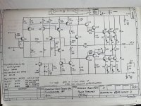
Thanks Saywer. Yep, definitely bipolar 220uF 6V and being replaced. I'd love somebody to explain the circuit to me as I don't fully understand it. I have emailed Cambridge for their permission to publish the full schematic as it has a copyright notice on it. There's only 6 electrolytic caps total, not including the filter caps, might just replace them all with new high quality ones just for insurance (this is a fully direct coupled design). I agree about the heatsinks. Might have to build a bigger dummy load and see what happens just for fun. I'd love to have a Quantasylum QA402 or 3 to test these properly, just cant justify it for hobby use.
I might end up selling these as I don't have speakers big enough or a preamp to suit (or a listening room to do them justice for that matter) so I want to make sure they are as good and reliable as I can get them. Still have to work out what that mod underneath one unit is and match on the other, then soak test and set the bias. Fun stuff. 🙂
I might end up selling these as I don't have speakers big enough or a preamp to suit (or a listening room to do them justice for that matter) so I want to make sure they are as good and reliable as I can get them. Still have to work out what that mod underneath one unit is and match on the other, then soak test and set the bias. Fun stuff. 🙂
Ok. Done with these. Bank of output transistors, a couple of driver transistors and resistors. New zeners in the inverter board that were a bit toasty. New bipolar caps and the few electrolytics. A couple of new trim pots, power switch repaired, new compliant moulded power cords, the right fuses, several dry joints and loose connections at the speaker terminals. They sound really great. I think the stated power output is a bit much given the size of the heatsinks (and how hot they got into my dummy load), but at normal levels they are perfectly fine. Been fun learning and fixing them up. Going off to be sold after electrical safety testing as they are too fancy for my meagre setup. 🙂. Hope some of this helps somebody later down the line. I do now have the manual.
All the best, Glenn.
All the best, Glenn.
- Home
- Amplifiers
- Solid State
- Cambridge A250 help