All my knowledge and experience are futile value if they went with me one day under the ground, and I have not conveyed to others!
Dr, is it possible to share pcb for calor ampl.?All my knowledge and experience are futile value if they went with me one day under the ground, and I have not conveyed to others!
Best regards .
Thimios.
Last edited:
O sorry Dr, just now i see this.Yes thimios, write directly on docacacak{at]gmail(dot)com
Thanks.
Regards.
Thimios.
Well said ... 😎All my knowledge and experience are futile value if they went with me one day under the ground, and I have not conveyed to others!
Would you mind if I derived from the calor to make a high power version
"slew" IPS ?
A question ... there seems to be 2 FB loops , one VFA/one CFA.
Does this split any voltage gain between the two stages ?
I was thinking of using a cheap standard dual op-amp , use one for servo ...
one for the main "deal" (amp). Also , standard hawksford as VAS.
OS
small progress in calor gold.
You must compare calor/eyesee . 2 "tricks" can get the same result. 😀
OS
Now you need to reveal trick detailsYou must compare calor/eyesee . 2 "tricks" can get the same result. 😀
OS

Last edited:
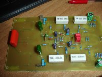
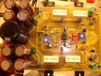
That's before first test fire!small progress in calor gold.
I must mention that i haven't all appropriate parts so some parts are for test conditions ONLY.
Attachments

Last edited:
That's before first test fire!
I must mention that i haven't all appropriate parts so some parts are only for testing conditions.
mean machine! 🙂
Can't wait... I hope I can hear the progress soonThat's before first test fire!
I must mention that i haven't all appropriate parts so some parts are for test conditions ONLY.
CALOR GOLD
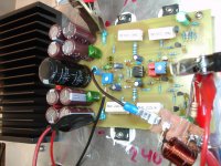
First test successfully ended.
First time, amplifier tested at +/-24v from two regulated power supplies.
Second test with two transformers ,one +/-16v and other +/-8v in series.
All under control.
All small signal transistors BC550C,560C.
Out fets IRFP240,9240.
Sorry Dr.but i have these on hand now.
Tomorrow i will have a small listening test.
Some pictures from first test.
I guess it is not permissible to show the copper side.
Attachments

I guess it is not permissible to show the copper side.
I hope you won't do that. Thank you!
I hope you won't do that. Thank you!
Why? Earlier you encouraged folks to build and test this amp.
Ok Dr.I hope you won't do that. Thank you!
Just a clarification. Two transformers are.1)2x16v a.c, 2)2x8v a.c.So the d.c (after rectifiers & series connection) is 2x31v d.c
Terry you can send mail to Dr. ,he will give you everything that is necessary.
Last edited:
Why? Earlier you encouraged folks to build and test this amp.
Because of such things... read from first post.
http://www.diyaudio.com/forums/solid-state/195351-80w-hybrid-audio-amplifier.html#post2686578
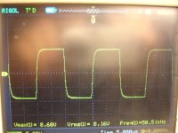
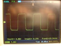
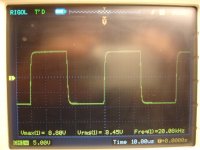
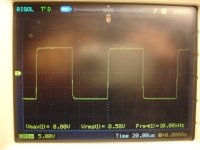
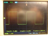
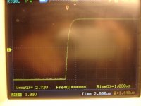
calor gold measurements.
Power suplly +/-30v
33.000uf/rail
R dummy=7R
Idle current =800mA./pair
1v RMS input give 20v RMS out./7R dummy=26db
20v RMS/7R=57W RMS just before clip.(1000Hz)
Power suplly +/-30v
33.000uf/rail
R dummy=7R
Idle current =800mA./pair
1v RMS input give 20v RMS out./7R dummy=26db
20v RMS/7R=57W RMS just before clip.(1000Hz)
Attachments
It looks almost like good amp...
An externally hosted image should be here but it was not working when we last tested it.
- Home
- Amplifiers
- Solid State
- Calor amp 40 Watts Class A