Talk about a thread dredge. It's ok I suppose when it is my dormant project.
It's been nearly ten years since the concept... time I actually built something.
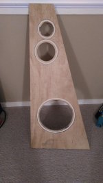
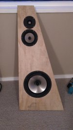
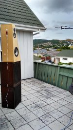
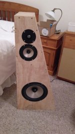
First a test baffle made from scrap. Will cut / assemble the rest of the enclosure tomorrow for the all important in cabinet frequency response measurements. Will be interesting to see how out my simulations were.
It's been nearly ten years since the concept... time I actually built something.
First a test baffle made from scrap. Will cut / assemble the rest of the enclosure tomorrow for the all important in cabinet frequency response measurements. Will be interesting to see how out my simulations were.
Attachments
Nice! Keep going and aim for completion by 2027 🙂
Now now now.... don't pile the pressure on me! 😀
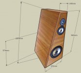
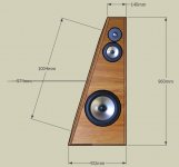
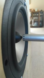
Here's the BDS geometry for the drivers..
Here's a conceptual picture of what they might end up like.
I hope you have seen the JBL 250Ti. Google that.
I hope you have seen the JBL 250Ti. Google that.
No I hadn't seen those. I didn't realise they copied moi? 😀
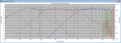
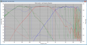
Here's actual measurements applied to my simulated x-over with a few component value tweaks. I used Jeff Bagby and Charlie Laub's FRD blender so I could use the nearfield of the L!5 and L26. I got good gated measurements outside
Attachments
Hi Dave,
Nice design - yes definately a bit reminiscent of a JBL 250Ti.
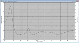
OK 2.4 ohm dip - that will be the 300uf in your bass filter for sure.
I built quite a few 3-ways using a similar 3rd filter on the bass driver & the max I could go on that cap was 150 uf otherwise I got a too low impedance dip.
Hey that looks like a tipical Wellington sky in your measurement photo.
I’m ex Wanganui.
Cheers & good luck with the design.
Clay
Nice design - yes definately a bit reminiscent of a JBL 250Ti.
OK 2.4 ohm dip - that will be the 300uf in your bass filter for sure.
I built quite a few 3-ways using a similar 3rd filter on the bass driver & the max I could go on that cap was 150 uf otherwise I got a too low impedance dip.
Hey that looks like a tipical Wellington sky in your measurement photo.
I’m ex Wanganui.
Cheers & good luck with the design.
Clay
Hi Dave,
Nice design - yes definately a bit reminiscent of a JBL 250Ti.
OK 2.4 ohm dip - that will be the 300uf in your bass filter for sure.
I built quite a few 3-ways using a similar 3rd filter on the bass driver & the max I could go on that cap was 150 uf otherwise I got a too low impedance dip.
Hey that looks like a tipical Wellington sky in your measurement photo.
I’m ex Wanganui.
Cheers & good luck with the design.
Clay
Thanks - yes - a calm day here for once. Suitable for measuring 🙂
Modifications made. 3.2 Ohm minimum I can (and hopefully my amp) live with.
I've tested this with nearfield and farfield gated HBT extracted and driver offset measurements.... plus also just farfield using actual SW phase. Both give identical xover summation. my in room response shows the appropriate amount of BSC has been applied to, to the L15. I ideally would measure off-axis responses too. then the only thing would be to make crossover alterations so I can get a more uniform power response, rather than perfect on-axis.
Attachments
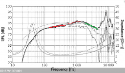
L15 vs W15 ?
G'day fella.
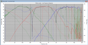
Yes. The red line is where the W15 is less sensitive and green = more sensitive.
Offline I've had a few PMs with a guy doing a W26/W15 design so was commenting on W15/L15 on-axis differences that would influence crossover adjustments but not fundamental changes to topology.
PS: I was doing more listening last night for previously forward / bright recordings. Good news is Brubeck sounds much better with a FLAC source. I must see what rip / encoding I was using before that cause me to hate it.
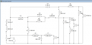
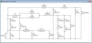
Daniel - latest xo, on-axis and impedance simulation. Actuals measure closely to my "hacked up" crossover (due to missing some component values needed). 2nd attachment is on-axis simulated (blue) and measured (red). I have more L15 notch breakup options to try / apply. Will post back
Attachments
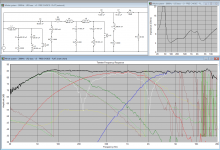
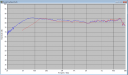
Daniel - latest xo, on-axis and impedance simulation. Actuals measure closely to my "hacked up" crossover (due to missing some component values needed). 2nd attachment is on-axis simulated (blue) and measured (red). I have more L15 notch breakup options to try / apply. Will post back
Thanks Dave! I'm gonna fab up a cabinet the same as yours and do in cabinet measurements, I'm rubbish at sims. I have enough crossover parts for any imaginable crossover.
Thanks Dave! I'm gonna fab up a cabinet the same as yours and do in cabinet measurements, I'm rubbish at sims. I have enough crossover parts for any imaginable crossover.
Cool. I'll post cabinet dimensions and driver placement info. Do you use Google Sketchup? I have a 3d model in that.
Cool. I'll post cabinet dimensions and driver placement info. Do you use Google Sketchup? I have a 3d model in that.
Sorry have not used google sketch up, dimension are fine.
Thanks
I'd like to see the Sketchup model. Can you post the entire project in a dropbox (or similar) account?
- Status
- Not open for further replies.
- Home
- Loudspeakers
- Multi-Way
- Calling Johan - Seas L26 + L18/L15 + 27TBFCG