Hmm, even an el cheapo Sounblaster Live has very lo noise and hum, provided you use its native 48 kHz sample frequency.
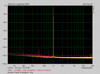
Attached a picture of a M-Audio Transit USB card. Red is powered directly from the PC, yellow is powered from an external powered hub, need I say more? Apart from this, Zero Cool is interested in levels > 1%.
😉
Attached a picture of a M-Audio Transit USB card. Red is powered directly from the PC, yellow is powered from an external powered hub, need I say more? Apart from this, Zero Cool is interested in levels > 1%.
😉
Attachments
There´s still one "problem". THD+N components are only recognized up to 20 KHz.
That is not so important for listening, but it CAN be important for the measuring results.
That is not so important for listening, but it CAN be important for the measuring results.
True, but you can measure harmonics separately as well as combined with a wideband true RMS meter. I assume it is known how THD and THD + noise is defined.
😉
😉
I think that´s exactly the problem when you want to align a 339 with a soundcard as source.
The unknown value of components in the 339 measuring range.
LP filtering will help, but it´s still hard to get clear results.
The unknown value of components in the 339 measuring range.
LP filtering will help, but it´s still hard to get clear results.
Hardi said:Some soundcards are too noisy while having a clean THD spectrum up zo 20 KHZ. There can be aliasing noise or low frequency hum....Also with some "good" cards.
The 339 measures everything (hum + noise) up to 110 KHz!
It´s also a good idea to use the HP339s 30 KHz filter in this case.
The THD section can measure THD of fundamentals up to 110 kHz, but harmonics up to 330 kHz are included in THD measurements unless rolled of by a low pass filter, according to the specs.
In post #22 you say "THD+N components are only recognized up to 20 KHz." What do you mean by that? The specs would seem to suggest that the instrument "recognizes" components up to 330 kHz (unless rolled off).
Pjotr said:Hmm, even an el cheapo Sounblaster Live has very lo noise and hum, provided you use its native 48 kHz sample frequency.
Attached a picture of a M-Audio Transit USB card. Red is powered directly from the PC, yellow is powered from an external powered hub, need I say more? Apart from this, Zero Cool is interested in levels > 1%.
😉
Can you show the spectrum up to 330 kHz?
The Electrician said:
Can you show the spectrum up to 330 kHz?
What’s your own opinion? No, of coarse not with a soundcard at 48 kHz sr. But as stated earlier you can see what the order of the residual D+N is of a 1 kHz sine with the HP 339A, even if it is not calibrated.
😉
Pjotr said:
What’s your own opinion? No, of coarse not with a soundcard at 48 kHz sr. But as stated earlier you can see what the order of the residual D+N is of a 1 kHz sine with the HP 339A, even if it is not calibrated.
😉
What's my opinion about what? Whether your spectrum analyzer can show the spectrum up to 330 kHz? I haven't the slightest idea what the capability of your spectrum analyzer might be; that's why I asked.
I can only see what the order of the residual D+N is below 20 kHz. How do we know that there aren't significant spurs above 20 kHz?
I think the issue Hardi is raising is, since the 339A sees spectral components up to 330 kHz, it would be good to know if the output of the sound card has any energy above 20 kHz.
IMO all suggestions so far are much too complicated.
An old-fashioned THD+N meter is nothing but an AC voltmeter with a switchable and tunable notch filter to filter out the fundamental.
You first set the total voltage as 100% then you notch out the fundamental and measure the remaining voltage as percentage of the first measurement.
So why don't you just feed the distortion meter a 1 kHz signal from a function generator at 1 kHz and set the reading to 100 % as the first step. Then you switch in the notch and tune to lowest reading. Then you tune the function generator to 2 kHz and feed the distortion meter a reduced level of this 2 kHz. I'd suggest that you do this by using a purpose-built switchable attenuator in order to make this fast and repeatable.
With this method it shouldn't be too difficult to check the accuracy of a THD meter even when the THD of the signal generator isn't very low.
Regards
Charles
Did you read post #9 and #12 in this thread? The method you describe has already been suggested, different only in minor details.
Post 9 and 12 are definitely not the same since my method uses only one signal generator, which doesn't even have to be of very high quality. The only thing that has to be precise is the voltage divider.
Regards
Charles
Regards
Charles
Most of the THD% Analyzers I have used are "auto-tune" -- not exactly a DIY project -- I did have an HD-1 from Heath, must have been early 1960's vintage -- and this was a manual null device.
The HP 3581 wave analyzer and HP 3586 selective level meters )and their GenRad cousins) will do just as you suggest.
The HP 3581 wave analyzer and HP 3586 selective level meters )and their GenRad cousins) will do just as you suggest.
In post #22 you say "THD+N components are only recognized up to 20 KHz." What do you mean by that?
20 KHz was referred to soundcard measurements with 44 KHz sampling rate.
😉
Any THD analyzer that has hopes of achieving a low floor will have auto tuning (as Jackinnj says) for both amplitude and phase. The Cordell diy unit docs explain this well. You need to keep the analyzer locked to the fundamental during calibration, so you need two sources, albeit one of them probably built in.
Apart from above, keep distortion figures in perspective. Getting distortion figures accurate < 1 % does make not much sense. If you get them 10% accurate you are doing not bad.
Distortion figures by itself does not tell much about the quality of the DUT, it is just a rough indication. The harmonic profile tells you much more, e.g. how fast and in what way the distortion spectrum decays.
😉
Distortion figures by itself does not tell much about the quality of the DUT, it is just a rough indication. The harmonic profile tells you much more, e.g. how fast and in what way the distortion spectrum decays.
😉
phase_accurate said:Post 9 and 12 are definitely not the same since my method uses only one signal generator, which doesn't even have to be of very high quality. The only thing that has to be precise is the voltage divider.
Regards
Charles
This thread is about checking the calibration of an HP 339A. That instrument auto-tunes, and a fundamental must be present for it to work properly. The instrument has a signal generator built-in, which could be used to provide the fundamental. A second generator could provide another, lower level sine wave to represent the distortion.
But, the fundamental must still be there. If it isn't there, the instrument won't show a distortion reading. So your method will still need two generators, one of them being the built-in one. I assumed you understood about the auto tune feature.
As, I said, different only in the details, at least as far as as what's being tested is a 339A.
I thought about using a PC sound card but will all the noise within a PC I was worried about what "junk" maybe riding on the line output that would cause inaccurate readings. I don't have a spectrum Analyzer on hand to be sure the output is clean.
Now i do have multiple sig gens on hand. so setting up a two tone signal i can do easy enough and yes the 339A has a built in Sig gen i can use as well.
And honestly, i don't need the test to be accurate out to .001% But if i could measure 10% and be within +/- 1% or so. just something that said hey the unit works and your in the ball park kind of thing.
BUT, this does give rise to an interesting product idea for a crafty person. someone could build a small box that runs off a 9V battery that is calibrated to some percentage and sell it. I would buy one!
Zc
The 339A isn't capable of .001% accuracy. :-(
But as I mentioned in post #13, a measurement would have to include harmonics up to the 867th to get .1% accuracy with a square wave input, so you would have to use a fundamental of no more than 380 Hz with the full bandwidth of the instrument.
If you're satisfied with 1% accuracy using a square wave, you only need to see up to the 87th harmonic, which would be about 3800 Hz with the full bandwidth of the instrument.
So, use a square wave of several volts amplitude and 1 uS or so rise time at 1 kHz, full bandwidth of the 339A, and you should get a distortion of close to the theoretical value of 43.5%. Or, use a triangle wave, and see something close to the theoretical value of 12.027%.
with RMAA you can test your soundcard in loopback mode for audio frequency spurs - even PC motherboard sound should be way better than your spec in the audio frequency range
by using 2nd or 3rd harmonic distortions a fairly simple filter could clean up the unseen spurs and noise past Nyquist without filter slope changing distortion frequency amplitude - again you can very accurately verify any filter effect on distortion by comparing loopback measurements in RMAA before and after filtering
by using 2nd or 3rd harmonic distortions a fairly simple filter could clean up the unseen spurs and noise past Nyquist without filter slope changing distortion frequency amplitude - again you can very accurately verify any filter effect on distortion by comparing loopback measurements in RMAA before and after filtering
The Electrician said:The 339A isn't capable of .001% accuracy. :-(
It will work down to a little above 0.001%, however --
- Status
- Not open for further replies.
- Home
- Design & Build
- Equipment & Tools
- Calibrated distortion source???