Hi Martin, thank you! Finally, I see where you got that п from, and it's a very useful derivation indeed. I shall remember that the RMS coefficient for a half-sine is 1/п.But, let me try once again:
Now, you corrected on the DC current equaling RMS current, but we are actually on the same page there, I do understand that the current through the PSU equals the current through the load.
It also seems to me you actually do need to spec your PSU for the full peak current, before dividing by п? Otherwise, you need to hope you have enough overload capacity. I wonder how smoothing capacitors - if there are any - come into play here, and how we can increase capacitance to decrease the current requirements for the current source itself.
Thank you, this is an awesome point that I did miss. It was optimistic to use the nominal speaker impedance of 8 Ohms in the calculations, instead I should take the minimum Re of an 8-Ohm speaker, 5 Ohms at max., if not lower. Also, if I were to go by my original calculations, I would end up with an amp that produces higher power into 8-Ohm load than 4-Ohm. On the other hand, if I calculate for 4 Ohms but all the speakers I have are 6 or 8, that's just wasted money on a beefy PSU.The max current depends on many things. Where your speaker min z is at. (the lower the freq the more current, bass has more energy). The speakers reactance
Also, I think calculating the requirements properly does matter even for transformers, although to a lesser extent. For example, I could order a transformer with 7 A secondaries and 1.5 Tl induction, or I could older a more expensive variant with the same 7 A spec, but 1.2 Tl induction. The former is closer to saturation, has lower reserve capacity.
Last edited:
well am i to think that air pressure variations and temperature in a solid (which is what Fourier was working on are congruent?) how does that account for losses due to phase...?
Not sure of your question. The phase of each sine is as important as its freq. and amplitude. The math keeps track of it. Thats the beauty of using the imaginary plane and Eulers formula/identity. Did you watch the video? Theres more in that series if things are not clear. You might need to start with
Euler's formula - Wikipedia
Euler's formula - Wikipedia
You have to make a reasonable assumption
how much power your speakers actually handle
So yes your building a 120 watt amplifier
but you might only use 15 to 40 watts of actual power.
Transformers are usually rated in Volt Amps
and conversion to watts is rather easy
1 Va = 1 watt
For Class A/B general rule of thumb for min transformer VA rating
is 2x amplifier power.
120 watt amplifier needs a 240 watt power supply.
so your looking at a 240 VA transformer
and 250 VA is pretty common.
And if you are running stereo pair
500 VA
120 watts RMS is about 5.5 amps
Each rail around 2.25 amps
Hej Alexium
SMPS'es are a totally different matter - this is where companies like Hypex, NL provides power supplies with a certain power rating and then allow for the expected peak current - thus allowing a peak current far above the current that represents the power rating.
Standard SMPS'es not designed specifically for audio amplifiers will typically as you imply need to be able to deliver the peak current which can only be done with a vastly "oversized" power rating.
The same applies for regulated power supplies in general.
A strategy for designing an unregulated power supply (and not going for "bigger is better") would be to use a transformer at least a little bit larger than the power I calculated in post #2.
As said - this is a muddy area.
Cheers,
Martin
This is what I meant by a simple unregulated power supply - the smooting capacitors will be able to handle the peak load if they are reasonably sized.It also seems to me you actually do need to spec your PSU for the full peak current, before dividing by п? Otherwise, you need to hope you have enough overload capacity. I wonder how smoothing capacitors - if there are any - come into play here, and how we can increase capacitance to decrease the current requirements for the current source itself.
SMPS'es are a totally different matter - this is where companies like Hypex, NL provides power supplies with a certain power rating and then allow for the expected peak current - thus allowing a peak current far above the current that represents the power rating.
Standard SMPS'es not designed specifically for audio amplifiers will typically as you imply need to be able to deliver the peak current which can only be done with a vastly "oversized" power rating.
The same applies for regulated power supplies in general.
A strategy for designing an unregulated power supply (and not going for "bigger is better") would be to use a transformer at least a little bit larger than the power I calculated in post #2.
As said - this is a muddy area.
Cheers,
Martin
As with heatsinks and power supplies
usually bigger is always better.
Then again most people are not going to blast away
at full power all the time.
Large capacitance in the power supply can help with current demand.
But the main objective is reducing the AC ripple.
And under heavy load, ripple can increase if the capacitance is not high enough.
Also remember at first startup
a large capacitor bank will cause a large
current spike. So if you start falling into the ridiculous sized capacitor banks.
You deal with ridiculous surge currents. Which will punch the rectifier in the face all its life.
If you dont go overkill with transformer or cap bank size.
You can get away with pretty basic thermistor soft start.
Another can of worms of opinions can erupt as soon as thermistor
gets mentioned.
Last edited:
I was going to mention thermistors as soon as I read to the point of "ridiculous surge currents". I've bought a simple soft start board with an array of thermistors and a time-delayed relay to short them out a couple seconds after turn on, seems to work quite well.
I'm from the school of ridiculous amount of PS caps, as it gets the ripple very low, and the amp 'disappears,' but you need to incrementally add more and more caps, so you're not paying for silence you can't hear.
While you're piling on the caps, you also want to add some CRC or CLC filtering, so you'll lose some rail voltage there.
I also have a pair of those L12-2 boards (allegedly the class A version) and expect to compare against my hopped-up Adcom 5200, so I'm aiming for about +/-40V rails, 5mV ripple.
While you're piling on the caps, you also want to add some CRC or CLC filtering, so you'll lose some rail voltage there.
I also have a pair of those L12-2 boards (allegedly the class A version) and expect to compare against my hopped-up Adcom 5200, so I'm aiming for about +/-40V rails, 5mV ripple.
I'm not sure if L12-2 should or even can work in pure class A. There has been a discussion of optimal bias current in the dedicated L12-2 thread, and the conclusion was that there is a sweetspot for the quiescent current, and it's quite low. Higher quiescent current - and distortion starts to rise.
What are the CRC / CLC filters for? I'd like to read more about it.
What are the CRC / CLC filters for? I'd like to read more about it.
Agree, and I'll try Calvin's way with those L12-2.
Higher-order low-pass filters....
I squeezed in extra L and C on a standard PassDIY F5 (which already had a small CRC setup), and the ripple went down by 1/50! (but also lost about 4 volts on the rails)
Higher-order low-pass filters....
I squeezed in extra L and C on a standard PassDIY F5 (which already had a small CRC setup), and the ripple went down by 1/50! (but also lost about 4 volts on the rails)
Attachments

Last edited:

Interesting. 4 volts of loss is not insignificant, though. And in decibels, the ripple reduction is not that awesome, I assume? Compared to active regulators that achieve at least -20 dB right away, -40 to -50 for more involved designs.
Do you like the F5? I have never heard about this amp before, looks interesting.
Do you like the F5? I have never heard about this amp before, looks interesting.
I looked at my notes, and it went from 50mV to 2mV of ripple and each rail lost 3.0V in the 4mH coil that I added.
That F5 belonged to a friend, and it got so piercing clean in the top end that he couldn't stand it and sold it to an enthusiastic local...
That F5 belonged to a friend, and it got so piercing clean in the top end that he couldn't stand it and sold it to an enthusiastic local...
Yes, I do like the F5 and expect to make dual-output transistor versions for myself, with around 35V rails and ~0.5F per channel.
Huge advocate of CLC supplies
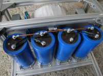
I have been modeling a few power supplies, different voltage and wattage transformers. I started using inductors in a few HOT ROD builds, I really like them. It is so hard to explain. As said, (I believe earlier in the thread) the amps disappear or get out of the way of the music. The system does an amazing disappearing act, driving the same speakers, fed by the same front end.
I cannot say enough good things about my recent CLC amp builds.
I follow the numbers that WhiteDragon gave as a baseline,
in line with my model / builds...
This supply has great stability and dynamic headroom.
Attachments
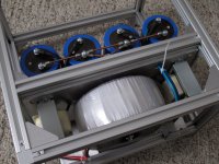
Super neat construction, thanks for sharing your awesome work! I have never thought to put the transformer sideways.
Did you calculate the CLC filter, is there a formula or a rule?
Did you calculate the CLC filter, is there a formula or a rule?
Super neat construction, thanks for sharing your awesome work! I have never thought to put the transformer sideways.
Did you calculate the CLC filter, is there a formula or a rule?
Thank you. I appreciate your comment. My imperative(s) were to isolate the toroid from the audio circuits, squeeze as much power into given chassis dimensions, and to orient the transformer for solid mechanical grounding. Another factor influencing this layout, was the length of the center-tap to reach the star ground point... oddly many things hinged around that important focal point.
I *marvel* those that would hand built to suit (and/or wish my approaches were, one to design and order (custom) parts) However, for this retired and very determined DIY'er, I use what is available, and in quantity (future proof). That said, I worked within "known standards". The Hammond 159ZL is wired with 12 gauge wire, rated at 10 amps, with "limited (virtually no) voltage loss" in the application, as shown.
The toroid is 1KVA Antek at 58volts, for a mono amp 350~500 watt power rating (using 6 dual die Exicons) for the output stage. This (dual mono, pair) power supply / amp is a beast, running Maggies with effortless ease.
resource for the question and topic
got me thinking about this, possible resources...
as amp building (to me) the PS is the heart,
seems so often neglected... misunderstood.
I have read through the amazing thread (before)
Bob Cordell Interview: Power Supplies
I am re-reading (up to page 45) have come across some real pearls...
so many very talented people are contributing there.
*others* may already know of this thread...
- Home
- Amplifiers
- Power Supplies
- Calculating current requirements of a PSU for a given power amplifier