Hi everyone,
Need help calculating resistors for cathode follower. Here is schematics:
Power supply will be 90V.
My estimate values:
RL = 3 kOhm
RB = 200 Ohm
RG = 100 kOhm
Cin = 2uF
Cout = 2uF
Need help calculating resistors for cathode follower. Here is schematics:
An externally hosted image should be here but it was not working when we last tested it.
Power supply will be 90V.
My estimate values:
RL = 3 kOhm
RB = 200 Ohm
RG = 100 kOhm
Cin = 2uF
Cout = 2uF
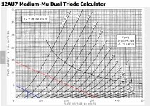
For close to 45V on cathode, Rb=390r and Rl=18k
From:

Ignore the red line, I just "borrowed" this graph from another page.
From:
Ignore the red line, I just "borrowed" this graph from another page.
Need help calculating resistors for cathode follower...
Essential design information missing. Maximum signal level and load impedance.
45V is half of your 90V B+. Generally the best place to start. Blue line.
Attachments
Last edited:
Load impedance 980 Ohm, max input level - CD or iPod
Hope you like distortion.
ideally Rk like a plate load resistor, should equal 2Xrp at the operating point - that's an awfully low Z but not a lot of voltage to swing
I'm assuming I should either increase voltage or load resistance? What would those be for operating without "distortion"? Thank you.
Why such low values? 😱
What are you trying to drive?
Any modern amp has at least 5 or 10K input impedance, many 100K to 1M .
I hope you are not trying to drive headphones, a simple cathode follower such as that is not up to the task.
What are you trying to drive?
Any modern amp has at least 5 or 10K input impedance, many 100K to 1M .
I hope you are not trying to drive headphones, a simple cathode follower such as that is not up to the task.
Why such low values? 😱
What are you trying to drive?
This is what I am wondering too.
The signal level is low and can be handled with a cathode follower having 90 V supply voltage, but the impedance is not suitable.
So whai is the device after the cathode follower ?
I visited the other thread and noticed your same question there.
Is this what you plan to drive with 12AU7 cathode follower ?
Is this what you plan to drive with 12AU7 cathode follower ?
An externally hosted image should be here but it was not working when we last tested it.
Then, I would use the non-inverting input of LM3886. So you can get suitable load impedance to the cathode follower.
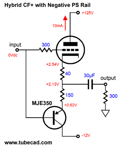
Like this:

I also recommend to study the application note of LM3886.
Like this:
I also recommend to study the application note of LM3886.
Then, I would use the non-inverting input of LM3886. So you can get suitable load impedance to the cathode follower.
Like this:
I also recommend to study the application note of LM3886.
If there is no solution for inverting schematics, I will go with noninverting. But I kind of want inverting variant. I studied lm3886 application note and also lm4780, which is two lm3886 in one chip, pg 23 has the inverting schematics.
Thanks
Just noticwd that with noninverting variant Cout for cathode follower can be much smaller than with inverting. Kind of tempting to use it... 🙂
Now I consider Cout as 20uF (for inverting 980 Ohms load)
Now I consider Cout as 20uF (for inverting 980 Ohms load)
Maybe the OP wants to build a 'tube buffer'? I.e. a mild FX box, as sold by hundreds of Chinese websites.
- Status
- Not open for further replies.
- Home
- Amplifiers
- Tubes / Valves
- Calculating cathode follower using 12AU7 for 90V supply