As I plan to build a Gainclone, I'd like to put a stepped attenuator instead of a pot on it.
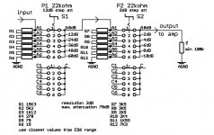
I already know a few things about how to cable it : it progressively shorts the output to ground after an input resistor which limits current and keeps input impedance high enough.
I will use two rotary switches (2poles * 6positions) in series, meaning there will always be 2 resistors in series, and allowing 36 different positions.
As I'm not so good at maths, I wondered how to calculate the resistors values, in order to get a linear acoustic attenuation.
I suppose it depends on the input impedance, and that it follows a log law, but I don't know how to use it.
😀
How easy it is to give a smoother attenuation to a part of the attenuation range ?
If anyone could help me, I'd be glad !

Hi,
The picture below shows one possibility.
On the audioXpress site http://www.audioxpress.com/magsdirx/ax/addenda/index.htm you can find a simple Excel spreadsheet (att.xls) for calculating attenuator values. There is also an article that goes with the spreadsheet, which was published in this month's issue of aX.
Regards,
Milan
Attachments
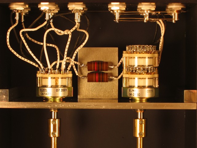
hello
other solution
what's my passive pre amp
the switcher is from elma 2x24

the sound is very clear
I can send you a photo where you can see the resistor range (for a 10kOhm stepped attenuator)
regards
Klang Projekt
other solution
An externally hosted image should be here but it was not working when we last tested it.
what's my passive pre amp
the switcher is from elma 2x24

the sound is very clear
I can send you a photo where you can see the resistor range (for a 10kOhm stepped attenuator)
regards
Klang Projekt
Nice realization ! Your preamp seems really well-built and shielded !
This is the stepped attenuator solution I wanted to use, variable steps of resistors that shorts input to ground.
I made some calculations with formulas found on the Net but, as I cannot obtain a 24 or 36 positions switch, I won't be able to use a stepped attenuator in my project.
The resistance range goes from 20K to 6R so it's impossible to cover the whole range using 2 switches with resistors in series as I thought it was possible before calculating the values.
It means I need at least 3 switches which is really not practical !
I'll put an ALPS inside, I suppose it's a good pot too for my first amp project 🙂
Thanks for your replies !
- Status
- Not open for further replies.
