Here's a formula for BL from an old thread:
The definition of Sd can't be right, because m^3 is a volume, not an area. What should it be?
Thankee.
Dave
Qes=1/(ws*Cms*Res) and
Cms=Vas/(rho0*c^2 *Sd^2) and
Res=(Bl)^2 / Re
Bl=sqrt((rho0*c^2*Sd^2*Re)/(ws*Vas*Qes))
rho0 = density of air =1.2 kg/m^3
c = velocity of sound = 345 m/s
Sd = Equivalent piston area in m^3
Re = voice coil DC resistance in ohm
ws = 2 *pi * fs
fs = free air resonant frequency of the driver in Hz
Vas = Volume equivalent to the cone suspension
Qes = "electrical" Q value of the driver
and sqrt... meaning the square root of ...
The definition of Sd can't be right, because m^3 is a volume, not an area. What should it be?
Thankee.
Dave
m^2, but I use this formula so that I can input Sd in cm^2 and Vas in liters:
BL = SQRT((rho*(c*0.0001)^2*Sd^2*Re)/((2*PI*Fs)*(Vas*0.001)*Qes))
It's nit-picking, but I've found the best correlation with actual measurements is when rho = 1.20997 kg/m^3 and c = 344.424m/sec..
GM
BL = SQRT((rho*(c*0.0001)^2*Sd^2*Re)/((2*PI*Fs)*(Vas*0.001)*Qes))
It's nit-picking, but I've found the best correlation with actual measurements is when rho = 1.20997 kg/m^3 and c = 344.424m/sec..
GM
Dave Jones said:The definition of Sd can't be right, because m^3 is a volume, not an area. What should it be?
[/B]
Yes, sorry, it should have been m^2.
GM said:m^2, but I use this formula so that I can input Sd in cm^2 and Vas in liters:
BL = SQRT((rho*(c*0.0001)^2*Sd^2*Re)/((2*PI*Fs)*(Vas*0.001)*Qes))
It's nit-picking, but I've found the best correlation with actual measurements is when rho = 1.20997 kg/m^3 and c = 344.424m/sec..
GM
Ahhhhhh.
BL = 1.1239
Thanks much.
Hmm, I double checked to make sure I didn't copy it wrong from my spreadsheet, so you must have done something wrong since it calcs to 4.5015 using the FE107E published specs, while Fostex lists it at 4.7. The difference being that theirs is calc'd using a different 'p' and 'rho'. You can sim using both to see the subtle difference it makes.
I can't imagine any driver having such a low BL.
GM
I can't imagine any driver having such a low BL.
GM
GM said:Hmm, I double checked to make sure I didn't copy it wrong from my spreadsheet, so you must have done something wrong since it calcs to 4.5015 using the FE107E published specs, while Fostex lists it at 4.7. The difference being that theirs is calc'd using a different 'p' and 'rho'. You can sim using both to see the subtle difference it makes.
I can't imagine any driver having such a low BL.
GM
When I use 4.5, the ML King spreadsheet graphs look ridiculous. I guess I'm doing something wrong.
Dunno. Since you have a licensed copy, send me your .mcd worksheet and a description of what you're trying to accomplish.
GM
GM
GM said:Dunno. Since you have a licensed copy, send me your .mcd worksheet and a description of what you're trying to accomplish.
GM
Thanks for the kind offer. I found my mistake, though. I miscalculated the effective cone area. I omitted pi. Doh!
It's looking pretty good now. I tried emailing it to you, but the diyAudio.com email thingy does not have a provision for attachments that I could find.
Here are the goals:
1. Cheap
2. Low enough bass to cross over to a sub at about 100 Hz (or below)
3. Small enough to fit a 15x15 ft office.
I'm actually going to build at least two sets of speakers. Only one set has to be inexpensive. But I'm doing the cheap one first.
A friend is going to build the cabinets. He's keen on using Fostex fe107e's. So be it. The fe107e has a small suckout between 400 and 600 Hz, so I've tried to put the transmission line 3F ripple right on top it.
Here's one design:
So = Sl = 30 in^2
L = 43 in
driver at 10"
0.75 lb/ft^3 stuffing top to bottom
Attachments
Hmm, I didn't check, just assumed you could. Anyhoo, your pipe is way too big/overstuffed. The only way to get solid/smooth output to 100Hz is in a ML-TL, though you won't be able to design in a 500-600Hz hump in the response. Of course you'll still need some BSC if not nearfield.
Max flat using published specs:
rp = 0.5"
Lp = 0.75"
density = 0.2lbs/ft^3
L (in)
15.38
S0/SL (in^2)
21.366
driver (in)
6.302
Vb(ft^3)
0.19
Fs or Fb (Hz)
83.9
GM
Max flat using published specs:
rp = 0.5"
Lp = 0.75"
density = 0.2lbs/ft^3
L (in)
15.38
S0/SL (in^2)
21.366
driver (in)
6.302
Vb(ft^3)
0.19
Fs or Fb (Hz)
83.9
GM
GM said:Hmm, I didn't check, just assumed you could. Anyhoo, your pipe is way too big/overstuffed. The only way to get solid/smooth output to 100Hz is in a ML-TL, though you won't be able to design in a 500-600Hz hump in the response. Of course you'll still need some BSC if not nearfield.
Max flat using published specs:
...etc
Dang! How did you do that?
Decades ago I did a bunch of studying and made lots of different 'proof of concept' designs based on mechanical resonance theory to arrive at a fairly accurate way to design tower designs (now ML-TL thanks to MJK).
I never did figure out a way to calc how much to shorten a vent based on tower length though. MJK solved it, but I'm too math challenged to understand it.
GM
I never did figure out a way to calc how much to shorten a vent based on tower length though. MJK solved it, but I'm too math challenged to understand it.
GM
GM said:Decades ago I did a bunch of studying and made lots of different 'proof of concept' designs based on mechanical resonance theory to arrive at a fairly accurate way to design tower designs (now ML-TL thanks to MJK).
I never did figure out a way to calc how much to shorten a vent based on tower length though. MJK solved it, but I'm too math challenged to understand it.
GM
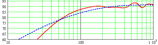
Well, here's the response curve. Pretty impressive!
Attachments

Looks just like mine! Imagine that. 😉 You can either make the vent longer or add a little damping material down at the vent if you want a 'tighter' impulse response, at the expense of some LF roll off of course.
How did you post the plot? I've never been able to figure it out. I mean I can do it with something from a website, but not from my computer.
GM
How did you post the plot? I've never been able to figure it out. I mean I can do it with something from a website, but not from my computer.
GM
GM said:Looks just like mine! Imagine that. 😉 You can either make the vent longer or add a little damping material down at the vent if you want a 'tighter' impulse response, at the expense of some LF roll off of course.
How did you post the plot? I've never been able to figure it out. I mean I can do it with something from a website, but not from my computer.
GM
I'm using MS Windoze.
I used a shareware utility called Snagit32 to capture the plot from the Martin King worksheet.
http://filedudes.siol.net/win95/scrncap/snagit.html
Save the plot as a PNG file.
Then, in your browser, at the bottom of the diyaudio edit page, just above the "submit reply" button, there's an area labeled "Attach File." Hit the "Choose" button, and navigate to the file you snagged with Snagit.
I didn't know about this type of program, thanks! I'd tried to preview stuff off my computer, but it wouldn't show up, plus it cleared the brower window, so I thought I couldn't do it. Guess I should have just gone ahead and tried it anyway.
GM
GM
GM said:Of course you'll still need some BSC if not nearfield.
GM
I'm ordering the parts today. What size inductors would you suggest?
GM said:
How about a ballpark figure?
I read that paper, and calculated L=1.5mH. The program edge.exe calculated 2.7 or thereabouts. I need a third opinion. 🙂
Dave
This guy goes to the doctor, and he says, "Doc, I hear voices."
The doctor says, "My diagnosis is you're crazy."
The guy says, "Doc, I want a second opinion."
The doctor says, "Okay, you're ughly, too."
Kind of tough to do when I don't now the speaker's dims or whether it will be setting on a desk/floor/whatever or up on a stand. Measuring is best of course, but you can get in the ballpark calcing it....... assuming they will be setting on a fairly solid area at least as big as the speaker's height (i.e. this constitutes the mirror image height), then (2*speaker height)*speaker width = effective area, which equates to SoS/((SQRT(area/pi))*2*pi) = Hz (-3dB). From this, an equivalent baffle width to plug into the formula can be calc'd: SoS/pi/Hz.
SoS = speed of sound. I use 1130ft/13,560in/344.428m/3,444.28cm/sec
GM
SoS = speed of sound. I use 1130ft/13,560in/344.428m/3,444.28cm/sec
GM
- Status
- Not open for further replies.
- Home
- Loudspeakers
- Multi-Way
- Calculate BL