Re: Reflecting on reflections
Fred Dieckmann said:"Are you saying that a mismatch introduces jitter?"
---------------------------------------------------------------------
It has been suggested to me that the best sounding connection for dCS upsampling 2 cable gear are two shorts runs of IEEE1394 cable. This seems to makes sense as the dCss are connected inside with 6 in or so of twited pair cables, terminating in 2 XLRs.
Anyone with ideas of charcteristic impedance of 4 wire and 6 wire IEEE 1394 cable and how to terminate in XLR?
The other other Fred
Re: Re: Reflecting on reflections
Isn't your input already terminated? You need just a cable, yes?fmak said:and how to terminate in XLR?
Got a Red Light
Hi Per-Anders,
I got a red light! I will not ride to death!
Congratulations, you won!!! You are the owner of the cosmic truth 🙄
Up to 5000++posts! Hurry, hurry, no time to loose!


 😀
😀
peranders said:
I think we can make this conclusion:
75 ohms out + 110 ohms cable(or do you have a 75 ohms?) + XLR-contact + 110 ohms input => sounds quite alright but you get a red light. Have you checked in the manual when this light is suppose to be lit? I suspect a weak signal because consumer signal is much weaker than a professional.
If it sounds great, why bother further? You could test to have the right connections and see if it makes any difference.
75 ohms out <-> 75 ohms cable <-> transformer 75 unbal -110 bal <-> 110 ohms cable <-> 110 ohms input.
Hi Per-Anders,
I got a red light! I will not ride to death!
Congratulations, you won!!! You are the owner of the cosmic truth 🙄
Up to 5000++posts! Hurry, hurry, no time to loose!
😀Re: Re: Re: Reflecting on reflections
No the questions is impedance of IEEE1394 4 wire and 6 wire cable and how best to terminate to an XLR.
-----------------------------------peranders said:
Isn't your input already terminated? You need just a cable, yes?
No the questions is impedance of IEEE1394 4 wire and 6 wire cable and how best to terminate to an XLR.
Based on measurements i have found the surprising conclusion that changing a coax cable from 50 cm to 150 cm did not change jitter performance at all. (Non terminated).
Proper termination of the cable also did not have influence on the jitter at the output of the cable.
It was measured on a steady clock (with 2pS jitter level 3-sigma) , the result might be different if you were to use a bi-phase modulated SP/DIF signal though.
Proper termination of the cable also did not have influence on the jitter at the output of the cable.
It was measured on a steady clock (with 2pS jitter level 3-sigma) , the result might be different if you were to use a bi-phase modulated SP/DIF signal though.
Interesting results Lars.
It must be wrong cause I said so also without any measurements.
Anyway, I think we are talking about different things here. Fred's book is about (I'll guess) digital communication with high speed and in such cases it's important to have control over speed in cable, losses, terminations, etc. The question is when these parameters start to matter.
Lars it's also interesting that you got 2 ps from a standard oscillator and Guido gets 6 ps from a special developed one (unkowned what the special thing was).
fmak, it seems very hard to get facts about FW cables. It's not so hard to measure the impedance if you have at least 10 m cable and a squarewave generator with fast rise time. The generator doesn't need to have same impedance as the cable. You just change the termination in the other end. It's clearly visible on an oscilloscope.
www.sigcon.com
"the result might be different if you were to use a bi-phase modulated SP/DIF signal though."
Yes it might................
I would back terminate clock lines even for
runs of a few inches. but then again I know what signal integrity is and actually measure and listen to the results of such efforts.
"the result might be different if you were to use a bi-phase modulated SP/DIF signal though."
Yes it might................
I would back terminate clock lines even for
runs of a few inches. but then again I know what signal integrity is and actually measure and listen to the results of such efforts.
Attachments

Oki, doki, wrong of me. Maybe it was that he could hear 6 ps?
Anyway, Lars have you tested a regular 2 USD oscillator also?
Anyway, Lars have you tested a regular 2 USD oscillator also?
Re: www.sigcon.com
I'm supplying clock signals with 4" and 6" runs. What's the best cable to use for that (shilded, unshielded, twisted pair?)
Also, should the ground (for clock signal) come from clock board (with ea signal), or is it OK just to provide signal alone and connect the ground from main PS?
Fred Dieckmann said:
I would back terminate clock lines even for
runs of a few inches
I'm supplying clock signals with 4" and 6" runs. What's the best cable to use for that (shilded, unshielded, twisted pair?)
Also, should the ground (for clock signal) come from clock board (with ea signal), or is it OK just to provide signal alone and connect the ground from main PS?
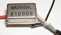
I tested one of those, and it actually measured quite good. 😉
This type: http://www.interquip.com/productInfo/pdf/7/146.pdf
Just a few dB from the limitation of my test equipment, but i think i can modify it and make a more accurate comparison. I will post here again if i can make some progress.
This type: http://www.interquip.com/productInfo/pdf/7/146.pdf
Just a few dB from the limitation of my test equipment, but i think i can modify it and make a more accurate comparison. I will post here again if i can make some progress.
Good grief, Lars...........
We are talking about bi-phase modulated signals, and cable length does matter in recovered jitter. As does the the quality of the termination.
Don't argue with me about this one.......
Jocko
We are talking about bi-phase modulated signals, and cable length does matter in recovered jitter. As does the the quality of the termination.
Don't argue with me about this one.......
Jocko
have Any Of You Actually Used One Of These ?...............
AFAIK the only red signal lights on the front panel of the DCX2496 are input and output level overload indicators.
Presumably the input gain controls are after the AES/EBU/SPDIF input stage.
The DCX2496 controller software is worth a look (565k download) http://www.behringer.com/DCX2496/DCX2496_v1-15.zip .
Eric.
- Status
- Not open for further replies.
- Home
- Source & Line
- Digital Source
- Cable termination