So let me ask you this question then: What is required for a SMPS to accept film caps and perform without any issues such as ripple ? If we improve the components used and this potentially create other issues, what has to change ?No I was just saying that if you think that you should put the same requirements to a power supply cap as to a signal coupling cap, that's wrong. Choose what is best for the application. Film caps in power supplies can lead to worse results just because they are lossless.
Jan
I see.. that kinda makes sense. I wish it wasn't so. What if all of the PSU and decoupling caps where PP-foil/film caps and you use shielding, the PSU in its own case, only delivering clean DC to the amplifier modules which is placed in its own chassi. Would that take care of the main ripple, RFI and EMI ?
Wherever you put the supply, don't use film caps, ues (lossy) elcaps.
Space between supply and amp can help with electromagnetic field hum and ripple; case in point is the sensitivity of SE output transformers to such fields, as many here have found to their dismay.
But that has nothing to do with the caps in the supply.
And don't for a minute think you can deliver 'clean DC' to an amp. There's only gradations of clean, and clear engineering measures to make it better or worse. Distance is good. Screening can help, but most EM at mains frequencies doesn't even see a few mm of alu.
Lossy elcaps help with absorption of the sharpest charge peaks, but film caps are a wrong choice for a PSU, except maybe in high frequency switched-mode power supplies. But we're not talking about that here.
Better spend that money on a good coupling cap.
Anecdote: many people buy a superreg in the diyaudio store, and have the great idea to replace the output elcap with a film cap. Only to have the supply oscillate. Here, the small ESR of an elcap is critical for the circuit stability. It's mentioned in the write -up, but hey, who reads that??
In fact, if you look into the data sheet of say an LM7815, there is a minimum loss resistance (ESR) that is required at the output for stability.
Sometimes loss is great, especially with stuff you don't want!
Jan
I don't know about others but I always read articles if they are available. If someone spend time to write and explain why certain things are they way they are and for a reason, why wouldn't I spend time absorbing that info, it is after all free... in most cases. I will take a look at that article as I am planning a preamplifier as well.
So to summaries, in power supply, one benefit from using el-caps because they absorb transient, ripple and peaks.
What sort of "rule" or range of lossy should one work with for PSU el-caps ?
So to summaries, in power supply, one benefit from using el-caps because they absorb transient, ripple and peaks.
What sort of "rule" or range of lossy should one work with for PSU el-caps ?
ALL components have parasitic behaviours, and sometimes you want particular ones.... For example, sometimes overly low ESR is NOT desirable, and replacing a old school ally electrolytic with a modern organic polymer part will actually cause serious problems (Right up to destroyed boards).
If for some reason I wanted to design a supply to take a particular type of cap (As opposed to the far more reasonable approach of picking the cap to suit what I am trying to design), I can do that, but it is a design issue.
To give a concrete example I have designed equipment for high temperature use 'down hole', electrolytic caps were right out in this application, we had to go ceramic, so I added explicit series resistance to avoid a high Q resonance with the supply cables that could have destroyed the electronics thru over voltage. In a design without the '30 minutes at 240C' constraint, I would just have used a jellybean electrolytic and it would have been fine without any special care.
A film cap is NOT in general better then an electrolytic, it is just different and has different behaviour and different tolerances, you use either one where it makes sense.
There is a certain tendency among audio folks (Don't really see it anywhere else) to think that 'lower is automatically better' (Lower ESR, Closer tolerance, lower feedback...), where these things are really just matters of engineering.
Remember that while an electrolytic may be -50, +100% or so, beta in a bipolar transistor can vary by a factor of at least 1000% between samples of the same part, and nobody worries about that.
A decent designer knows how the parts they select will behave, including how the non 'ideal' aspects will behave and uses that knowledge, those 'non ideal' behaviours can be been selected with some care.
Consider for example that a film cap will usually be much larger then a same valued electrolytic, so if you stuff it into the same footprint it will invariably have more loop area in play, now possibly I don't want loop area (= inductance = higher ripple even if the part itself looks superficially better) so I deliberately did not use the massive film part.
Now sometimes BOM cost considerations force the issue and I would rather use something else, but you can never be sure that was the case, and maybe I put some thought into that electrolytic.... By all means sub other parts, but measure before and after, making something sound different is **EASY**, making something sound really, genuinely **Better** is much harder (And usually involves loudspeakers or room acoustics).
Dan Mills.
Member
Joined 2009
Paid Member
back to the thread title - I really like C0G capacitors as I find they are readily available, reasonably priced, compact enough and I have no qualms about their performance whatsoever. I've never tried paralleling them. I use them for amplifier feedback compensation and for MOSFET anti-oscillation zobels. When used as Cdom I have found them to sound cleaner than a silver-mica cap (a rather subtle subjective evaluation on one amplifier only).
So let me ask you this question then: What is required for a SMPS to accept film caps and perform without any issues such as ripple ? If we improve the components used and this potentially create other issues, what has to change ?
You can't get away from ripple. You can only make it smaller. In an SMPS you try to increase frequency because that means that charge cycles come with shorter periods, and that gives lower ripple in amplitude, but of course higher in frequency.
At very high frequencies a film cap could be good because if it has low inductance so they still work at the high frequency, where elcaps are almost invisible due to inductance.
The problem with film caps in SMPS is their size which again increases inductance, so the move then is to ceramics like COG/NPO. Make the layout very compact to minimize inductance that has a large impact at 1MHz!
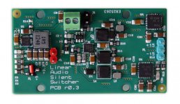
In my SilentSwitcher, which switches at 1.1MHz, I use parallel 20uF COG ceramics. You can see them on the PCB.
Jan
Attachments
Last edited:
Are does the 1206/3216 size ?In my SilentSwitcher, which switches at 1.1MHz, I use parallel 20uF COG ceramics. You can see them on the PCB.
Jan
I am glad I created this thread. I had a feeling it would generate interest and I will simply have to live with the fact that el-caps are needed. I can use film caps in other places and an indication is that Wima FPK could perform better than C0G even as shown via vicnic's data.
Low-distortion Audio-range Oscillator
You can't get away from ripple. You can only make it smaller. In an SMPS you try to increase frequency because that means that charge cycles come with shorter periods, and that gives lower ripple in amplitude, but of course higher in frequency.
At very high frequencies a film cap could be good because if it has low inductance so they still work at the high frequency, where elcaps are almost invisible due to inductance.
The problem with film caps in SMPS is their size which again increases inductance, so the move then is to ceramics like COG/NPO. Make the layout very compact to minimize inductance that has a large impact at 1MHz!
In my SilentSwitcher, which switches at 1.1MHz, I use parallel 20uF COG ceramics. You can see them on the PCB.
Jan
You mean X5R or X7R right? A 20uF C0G would be massive.
You mean X5R or X7R right? A 20uF C0G would be massive.
Hmmm, don't remember. Will check.
Edit Yes, XR5, Mouse 81-GRM31CR61E226KE5L
Good catch.
Jan
Last edited:
Are does the 1206/3216 size ?
I am glad I created this thread. I had a feeling it would generate interest and I will simply have to live with the fact that el-caps are needed. I can use film caps in other places and an indication is that Wima FPK could perform better than C0G even as shown via vicnic's data.
Low-distortion Audio-range Oscillator
Film caps, especially with wound construction are not suited for power supply use. Even stacked construction will have higher inductance than MLCCs. Like others mentioned, high Q is not your friend here necessarily.
Interesting. Do you have a comparison or some data here ? - specifically against foil caps.Film caps, especially with wound construction are not suited for power supply use. Even stacked construction will have higher inductance than MLCCs. Like others mentioned, high Q is not your friend here necessarily.
Interesting. Do you have a comparison or some data here ? - specifically against foil caps.
No, but just look at the physical sizes. They are not for decoupling.
Looks like Rubicon PLMCAP might outperform MLCC ... (with a question mark)
Product Information: PMLCAP Technical Notes/Capacitor, Power Supply Units RUBYCON CORPORATION
Product Information: PMLCAP Technical Notes/Capacitor, Power Supply Units RUBYCON CORPORATION
Looks like Rubicon PLMCAP might outperform MLCC ... (with a question mark)
Product Information: PMLCAP Technical Notes/Capacitor, Power Supply Units RUBYCON CORPORATION
In what way?
Jan
Don't shoot the messenger 🙂In what way?
Jan
Some notes:
«Impedance/ESR characteristics»
As an example, the frequency characteristics of impedance and equivalent series resistance (ESR) of 35 V 10 µF (5750 size) is shown. PMLCAP has excellent frequency characteristics of low ESR and equivalent series inductance (ESL).

«Harmonic distortion ratio»
In audio equipment, distortion characteristics can be a hindering factor in playback of the original sound, so low distortion PMLCAP is increasingly adopted, especially for high quality audio equipment that prioritizes sound quality.
In contrast to PMLCAP, high dielectric constant type MLCC tends to have higher harmonic distortion rate due to voltage dependent impedance change.
PMLCAP is effective in improving sound quality since it has a structure with a very high interlayer adhesion by a laminate production technique by continuous vapor deposition of a dielectric layer and an internal electrode layer in a vacuum, and furthermore, it is made up of the external electrode excluding the magnetic material

There is more on the webpage
Don't shoot the messenger 🙂
Some notes:
«Impedance/ESR characteristics»
As an example, the frequency characteristics of impedance and equivalent series resistance (ESR) of 35 V 10 µF (5750 size) is shown. PMLCAP has excellent frequency characteristics of low ESR and equivalent series inductance (ESL).
«Harmonic distortion ratio»
In audio equipment, distortion characteristics can be a hindering factor in playback of the original sound, so low distortion PMLCAP is increasingly adopted, especially for high quality audio equipment that prioritizes sound quality.
In contrast to PMLCAP, high dielectric constant type MLCC tends to have higher harmonic distortion rate due to voltage dependent impedance change.
PMLCAP is effective in improving sound quality since it has a structure with a very high interlayer adhesion by a laminate production technique by continuous vapor deposition of a dielectric layer and an internal electrode layer in a vacuum, and furthermore, it is made up of the external electrode excluding the magnetic material
There is more on the webpage
Yes, for coupling applications. Not for decoupling though.
https://product.tdk.com/en/products/emc/guidebook/eemc_product_01.pdf
You seem hellbent on replacing the caps, but what do you hope to gain?
Meh, 10uF series resonance at ~500KHz, so 10nH or so?
Nobody is seriously advocating for type II dielectric MLCCs for filters (which are the only places that a cap should have volts of signal across it), that IS film (or in low values, C0G) territory.
Different parts for different jobs, but know what job you are trying to do before deciding on the part.
Regards, Dan.
That is one way to look at it 🙂.You seem hellbent on replacing the caps, but what do you hope to gain?
Basically, it all started with: "Heat kill electrolytic capacitors, they dry out and increase the ESR" Its not like we are talking 2-3 decades, 10 years or less is more than enough time for el-caps to fail. Many have poor TCR value over there operational temperature range. Dielectric absorption etc... That is why when I read about Wima DC-Link which was developed to replace el-caps in power supply's as an example, that made me very happy.
I hope to gain components that is stable, don't fail, that is thermally stable, has low ESR and ESL, don't dry out, is fairly linear over the useful frequency range and so on. I am not looking at cost, I am looking at performance and endurance.
- Are we doomed to use electrolytic for decoupling til the end of time ?
That is one way to look at it 🙂.
Basically, it all started with: "Heat kill electrolytic capacitors, they dry out and increase the ESR" Its not like we are talking 2-3 decades, 10 years or less is more than enough time for el-caps to fail. Many have poor TCR value over there operational temperature range. Dielectric absorption etc... That is why when I read about Wima DC-Link which was developed to replace el-caps in power supply's as an example, that made me very happy.
I hope to gain components that is stable, don't fail, that is thermally stable, has low ESR and ESL, don't dry out, is fairly linear over the useful frequency range and so on. I am not looking at cost, I am looking at performance and endurance.
- Are we doomed to use electrolytic for decoupling til the end of time ?
For bulk decoupling maybe, but ceramics are better in general. They are just limited by value.
Anyway if you just want reliability, replace the electrolytics with hybrid polymer electrolytic caps. They make with ratings up to 10000 hrs + @ 105C.
Conductive Polymer Hybrid Aluminum Electrolytic Capacitors | Industrial Devices & Solutions | Panasonic
- Status
- Not open for further replies.
- Home
- Design & Build
- Parts
- C0G/NP0 Parallel-Capacitor-Board