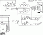
This will be my first proper electronics project. I'm just looking around first, wondering where to start. I couldn't find the info I need through a search so far. Maybe I'm searching for the wrong things. I just want to say how I'm thinking and if someone sees fit to give me a push in the right direction it would be much appreciated.
The DAC I am bypassing is an 18bit UDP63200 NEC unit
I will be sending the signal to a Chinese Zero DAC that utilises AD1852 and CS8416. Then I will play with the Opamps.. (DAC goes to Sugden A48 driving homemade Kef CS7 units utilising Malcolm Jone's no.53 crossover with upgraded PP caps).
SO... I think I need to build an electronic circuit that obtains a high quality S/pdif signal out of the dac0R, dac0L, word clock, and Q clock. Then feed the zero DAC with this.
Anyway, maybe I'm being totally ****-eyed with this thinking.. I'm just in learning phase.. Any advice appreciated.. Portion of VL70-m schematic attached.
Cheers
Attachments
I suppose the biggest question I have at the moment is what are the components of a s/pdif signal? And how do the four components I have identified relate to these? Are they at the right voltages etc?
Then, the circuit that I will need to design to make my s/pdif signal - how can I design it, what quality components should I use, to ensure the most accurate, smooth s/pdif signal possible?
Then, the circuit that I will need to design to make my s/pdif signal - how can I design it, what quality components should I use, to ensure the most accurate, smooth s/pdif signal possible?
That isn't I2S but that is the least of your problems. The data is oversampled by at least four times, most likely eight. At 192k, with a bit of fancy digital footwork, you might get away with it but at 384K, the CS8416 won't pass it and the AD1852 won't play it. What you really need is more information on the HD62098 and whether or not it has a SPDIF output.
But the specs on the zero say it is a 192kHz/24bit DAC. So, if it was 192kHz that would be perfect, no?
Thanks for the advice. I have been emailing hitachi trying to get info on this chip. Nothing seems to be available on the net.
Would the spdif output not be labelled on the chip? The schematic I attached has all the chip ports labelled. I just am unable to make head nor tail of them myself apart from the word clock and master clock.
- Status
- Not open for further replies.
- Home
- Source & Line
- Digital Source
- Bypassing the DAC in a VL70-m physical modelling synth
