Your cathode cap shows as 47uF Elec so it will be polarity sensitive.
If you are sure that there should be a 12AX7 in where the 12AU7 is then, Yes that will effect the overdrive!
And yes it is done to make the amp run clean!
Regards
M. Gregg
If you are sure that there should be a 12AX7 in where the 12AU7 is then, Yes that will effect the overdrive!
And yes it is done to make the amp run clean!
Regards
M. Gregg
Hi Guy's thanks for all the help with this, I really appreciate it.
After seeing the schematic M Gregg posted & this amp having a 12AU7 Valve instead of a 12AX7 valve as in the schematic I thought I had better contact the original owner & ask some questions.
Apparently the amp had been to a repairer to service it & on return to the owner it was never the same, I think that may say it all as it was then sold & of course to me.
I got it cheap though & it's worth fixing, I am a Luthier & will use it as a tool of the trade so to speak.
Ok, I then had a very close look at the power valves, as I mentioned earlier on, they looked a little different.
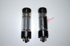
One is Marked 6CA7/EL34 on the base, it's been scribed in.
The other valve has no markings at all, you can see where it was printed on the valve itself but has been worn off & you can't read it.
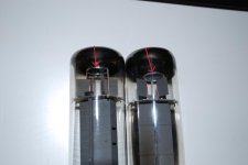
On closer inspection the internals of the valves are are slightly different, I'll try to get this right, correct me if i'm wrong.
The one that is scribed has the getter ring in the top of the valve connected by two points.
The other unmarked one has the getter ring connected by only one point & is 90deg different than the other valve..
There is a metalic deposit on the top of one & on the top & side of the unmarked one.
I'm not sure if these differences will hurt anything or cause the problem but I thought it may be the best place to start & clear this up first before going on. The base pins in relation to the locator slot are identical.
If it is an issue I will have to wait until some new valves turn up before proceeding.
Wavebourn asked if I had a DMM, yes i have a bit of equipment, an O'scope signal generators etc etc but have never worked with valves before.
It's time I learn more.
I have attached some pictures of the valves & you will see the differences.
Let me know if there ok to use & I will work through all of the previous suggestions & post the results.
Thank again Guy's
Cheers
After seeing the schematic M Gregg posted & this amp having a 12AU7 Valve instead of a 12AX7 valve as in the schematic I thought I had better contact the original owner & ask some questions.
Apparently the amp had been to a repairer to service it & on return to the owner it was never the same, I think that may say it all as it was then sold & of course to me.
I got it cheap though & it's worth fixing, I am a Luthier & will use it as a tool of the trade so to speak.
Ok, I then had a very close look at the power valves, as I mentioned earlier on, they looked a little different.
One is Marked 6CA7/EL34 on the base, it's been scribed in.
The other valve has no markings at all, you can see where it was printed on the valve itself but has been worn off & you can't read it.
On closer inspection the internals of the valves are are slightly different, I'll try to get this right, correct me if i'm wrong.
The one that is scribed has the getter ring in the top of the valve connected by two points.
The other unmarked one has the getter ring connected by only one point & is 90deg different than the other valve..
There is a metalic deposit on the top of one & on the top & side of the unmarked one.
I'm not sure if these differences will hurt anything or cause the problem but I thought it may be the best place to start & clear this up first before going on. The base pins in relation to the locator slot are identical.
If it is an issue I will have to wait until some new valves turn up before proceeding.
Wavebourn asked if I had a DMM, yes i have a bit of equipment, an O'scope signal generators etc etc but have never worked with valves before.
It's time I learn more.
I have attached some pictures of the valves & you will see the differences.
Let me know if there ok to use & I will work through all of the previous suggestions & post the results.
Thank again Guy's
Cheers
Attachments
Last edited:
Sorry for the double post,
I forgot to mention it is the valve that is marked 6CA7/EL34 that is running hot, it will run hot in both output sockets.
Cheers
I forgot to mention it is the valve that is marked 6CA7/EL34 that is running hot, it will run hot in both output sockets.
Cheers
Both tubes look like EL34.
My advice is to get the amp into spec. EL34s can have a few variations. Where the getter is does not matter. If its an EL34 then it should work in the amp. I know we like matched tubes,however get your amp working within the spec for the valves. (why trash new tubes for testing!)
The fact that one valve is running so high shows a problem. You can measure the voltage on the cathode resistor to ground. Use ohms law to calculate the current in the resistor. This will give the current in the tubes, However because the tubes are using the same resistor you will not know how much is in each one! Calc is voltage on resistor divided by resistance of resistor = current.
Anodes "plates" must not run so they are RED! It is obvious that you have to much current! You could try some new old tubes!
Your amp will hold HT after switch off, Take care!
Regards
M. Gregg
Last edited:
There may be 2 causes: either hot tube has gas inside so runs away, or another lost emission.
About your buzz: if it is the same as on Youtube, something resonates mechanically that has bad electrical contact.
About your buzz: if it is the same as on Youtube, something resonates mechanically that has bad electrical contact.
Last edited:
Gday Guy's
I've had an interesting morning looking at the amp, I found the Cathode capacitor was bad & not reading at all on the DMM so I replaced it & tested the Cathode current as mentioned.
It was around 125mA but seeing as there is only one cathode resistor it didn't really tell me much.
I guess if the valves were matched you would divide that by 2 & have 62.5mA each but there not matched & different brands. One valve was still glowing red.
I then decided to change the circuit a little & have a Cathode resistor & capacitor for each valve to see what is going on. This has certainly fixed the issue with the hot valve as it is not glowing red now.
The original single resistor was 180 Ohms so I doubled that for each valve & the closest I could get was 370 Ohms with the Resistors I have here at the moment.
Just a quick question before I forget, how many watts does the Cathode resistor have to be for this amp, I used 5W which to me seems like it should be ok? There's not much power there.
The Cathode currents now are 40mA & 67mA respectively on each valve The 67mA is the valve that was running hot so it seems to draw more current than the other.
I had a look at the datasheet but I am unsure what class this amplifier is so I am not exactly sure where I should now set the Cathode current, could someone help me with that please.
Once I know this I can set it up correctly.
I have read that you should set the Idle current to 70% of maximum & then with a signal it can raise by up to 30% with the guitar.
Is this correct?
Another question, when testing the idle currents voltages etc, is it necessary to have a load on the amp under test, I wasn't sure about this so I had the speaker cab plugged in just incase.
This also helped me discharge the caps before working on it.
Another question, the heater voltage seems to low at around 3.5v which is not right, this is loaded with the valves in. As far as I have read this has a big effect on the performance of the amp, is this correct.
If so I would like to fix that issue as well.
Sorry for all the questions but if you don't ask you don't know.
Some of the component values & a couple of other things are a little different in this amp compared to the schematic that was posted so I will draw this one & post it when done.
Cheers
Last edited:
O.K. Lets take it one step at a time!
Easy questions first!
Heaters on EL34 should be 6.3V.
Current at idle I would expect to be approx 50mA
So I would try changing the coupling caps 100nF same as 0.1 to polyprop at 1000v WKG. That may reduce your idle current.
Your cathode load 5W is O.K. I would have used 10W only because a flash over in a tube will destroy the resistor. However you have shared the current.
Class is going to be AB.
Yes make sure you have a load on the amp. when testing a large wattage resistor is a good bet at 4/8/16 Ohm to match your speaker. Because if you short something by accident you may damage your speaker!🙂
Regards
M. Gregg
It is a good idea to put a 1Mohm 2W or higher wattage resistor across your HT caps so you get a slow discharge after power off. It may save you if you take a break and come back having not discharged the HT supply! I always fit one as a permanent safety measure! Just a thought has the amp got a voltage selector for the mains?
Regards
M. Gregg
Regards
M. Gregg
Last edited:
Well measure the bias voltage, will you ? This will tell you whether the reason for one tube running hot is incorrect bias or defective tube.
Well measure the bias voltage, will you ? This will tell you whether the reason for one tube running hot is incorrect bias or defective tube.
Can you give us the values of the HT voltage.
Bias voltage on each of the tubes and bias supply.
Heater voltage on all power tubes.
Also the heater voltage on the gain stages.
🙂
Regards
M. Gregg
Quote.
Another question, the heater voltage seems to low at around 3.5v which is not right.
If these are AC and you have measured at the correct point then your mains input is not correct!🙂
This will effect everything Bias HT etc.
Regards
M. Gregg
Another question, the heater voltage seems to low at around 3.5v which is not right.
If these are AC and you have measured at the correct point then your mains input is not correct!🙂
This will effect everything Bias HT etc.
Regards
M. Gregg
- Status
- Not open for further replies.
- Home
- Live Sound
- Instruments and Amps
- Buzz In Guitar Amp