Hello,
I am having trouble removing a hum/buzz from an amp.
The hum's volume is the same as quiet music.
I built the amp a couple of years ago, gave up fixing the hum, and have taken it up again.
Its a Matrix amplifier, based off circuits from:
Steve's Tube Pages MATRIX
The problem only happens in the left channel.
With the left or right input connected, no hum.
Left AND right input connected, hum appears.
Moved ground leads of inputs to different locations, hum remains.
Tested feedback from grid of left signal triode, to inverting triode, hum was halved.
Removed mains ac lead while signal is playing (until B+ drops), hum disapears.
Tested signal with laptop running from battery, hum disapears.
Any help would is greatly appreciated.
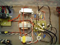
(The photo has the left input bypassing the inverting triode,
I was just testing to see if the heater wires were affecting it.)
I am having trouble removing a hum/buzz from an amp.
The hum's volume is the same as quiet music.
I built the amp a couple of years ago, gave up fixing the hum, and have taken it up again.
Its a Matrix amplifier, based off circuits from:
Steve's Tube Pages MATRIX
The problem only happens in the left channel.
With the left or right input connected, no hum.
Left AND right input connected, hum appears.
Moved ground leads of inputs to different locations, hum remains.
Tested feedback from grid of left signal triode, to inverting triode, hum was halved.
Removed mains ac lead while signal is playing (until B+ drops), hum disapears.
Tested signal with laptop running from battery, hum disapears.
Any help would is greatly appreciated.
(The photo has the left input bypassing the inverting triode,
I was just testing to see if the heater wires were affecting it.)
Attachments
Perhaps you could start with separating your high mains ripple power supply circuitry - and bring the 0V from the last filter cap over to the star ground point.
Also perhaps move your star ground point to the last filter cap of the B+ supply, and separate the ground returns from the output valves, from those of the input valves, and don't ground the input sockets at the socket.
Also perhaps move your star ground point to the last filter cap of the B+ supply, and separate the ground returns from the output valves, from those of the input valves, and don't ground the input sockets at the socket.
Your hum loop appears to include the mains earth, based on your initial comments. How many 0V points do you have that go to the chassis? Does the mains protective earth go to the chassis by itself?
Have you tried other 'nice hi-fi style' signal sources that are mains powered - using the same 'matrix of connection combinations.
Have you tried other 'nice hi-fi style' signal sources that are mains powered - using the same 'matrix of connection combinations.
The chassis is connect to earth only at one point with a bolt.
I used that bolt as the center of the star.
The only 0v running through the chassis, is the shield of the inputs.
Input cable is a twisted pair with a seperate outer shield.
Had previously tested with the shield disconnected, but the buzz was still there.
My only mains powered audio source, with earth, is a PC.
My Laptop and Turntable don't have a direct connection to earth.
It's only with the PC connected that the problem appears.
So the PC is injecting hum into the ground loop created when plugging in both channels. Remember that PC PSU designers don't think about audio.
Generally not a good idea to combine the signal star point with the safety chassis ground, as you can lose control of where your currents go.
Generally not a good idea to combine the signal star point with the safety chassis ground, as you can lose control of where your currents go.
You indicated that when the laptop was battery powered, then you didn't get hum when just one channel was connected, but you got hum when both channels are connected.
Was that hum the same type/sound as any other time you've noticed hum?
Do you have separate channel outputs from the laptop, or just a 3.5mm jack with a common ground?
Have you taken each channel from the laptop jack using a separate twisted pair over to the input sockets on the amp chassis?
I think you indicated the amp input sockets were isolated from chassis, and the incoming channel 0V was terminated at star point for each channel?
Have you tried a simple shielded stereo cable from the laptop, using just the normal shield as the 0V, and then splitting the channel wires out of the cable when near to the valve inputs?
what you should do is electrically isolate the pc by inserting a 1:1 transformer (ideally)
a short cut if the problem is with dc coupling, you can try a 1uf poly cap to ac couple (only works if the noise is not on the ground side of the source).
if it was happing with any source or no source hooked up, it would be a bad center tap on the heater.
a short cut if the problem is with dc coupling, you can try a 1uf poly cap to ac couple (only works if the noise is not on the ground side of the source).
if it was happing with any source or no source hooked up, it would be a bad center tap on the heater.
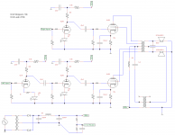
You have three amplifying stages on the left channel and two on the right channel and the right and left channels use the same output transformer? That's an interesting design?? Looks like it's designed to humm?? Where did you get the schematic?
But see here to read about how a Matrix amplifier is supposed to work....
The Matrix Amplifier
It's an interesting, if unconventional topology.
I tried different input connections and measuring the peak-to-peak output voltage with a scope:
Voltage listed is from left output.
Output voltage is roughly the same for each channel, except when testing with the desktop PC. Then the left channel is much larger.
Hum, was a 50hz sine wave.
Buzz was 100hz pulses.
Voltage listed is from left output.
Output voltage is roughly the same for each channel, except when testing with the desktop PC. Then the left channel is much larger.
Hum, was a 50hz sine wave.
Buzz was 100hz pulses.
Code:
both 6lr8 triode grids shorted to cathode - 2mv
left 6FJ7 shorted, right 6lr8 shorted 	- 20mv, hum.
input sockets shorted 		 	- 10mv, hum + buzz
left socket shorted, right open 	- 10mv, hum + buzz
left socket open, right shorted 	- 40mv, buzz
input socket open 		 	- 40mv, buzz

input from Desktop PC 		 	- 150mv, buzz
input from Desktop PC, left disconnected - 45mv, buzz
from PC, right channel disconnected 	- 300mv, buzz

input from Laptop - 30mv hum + staticI have just been using a 3.5mm jack to 2xRCA cable.Do you have separate channel outputs from the laptop, or just a 3.5mm jack with a common ground?
I test with the same cable for both laptop and desktop pc.
In the original photo, you can see on the righthand side, a turret board.I think you indicated the amp input sockets were isolated from chassis, and the incoming channel 0V was terminated at star point for each channel?
This has a bus bar for most of the audio circuitry.
The inputs are connected to this bus.
Originally the turret board was terminated at the psu turret board,
but I now have it terminated at the star ground.
I'll have to think about how to implement this.Generally not a good idea to combine the signal star point with the safety chassis ground, as you can lose control of where your currents go.
12E1 very cool. On the link 12E1 posted Steve Bench had a balance pot on the right input AND a 120K resistor. This would infer as you found above one channel is louder? Have you tried balancing the signals with a pot on the right input (In your case LEFT input)?
Also check right at your input that the resistance to ground is correct. From experience those shielded cables have a nasty habit of partially shorting to the shield if they are not trimmed out well.
Steve also found that Power Out goes up with both channels driven. Welcome to the Matrix.
Also check right at your input that the resistance to ground is correct. From experience those shielded cables have a nasty habit of partially shorting to the shield if they are not trimmed out well.
Steve also found that Power Out goes up with both channels driven. Welcome to the Matrix.
After moving all star ground points to the final PSU cap,
The hum has been halved.
The major offender was the CT from the B+ transformer.
Added a volume pot.
Turning it most of the way down reduced the hum even more.
Thanks for all the suggestions
Finally got around to adjusting it on the amp. Didn't reduce the hum but has made it easier to use.
The hum has been halved.
The major offender was the CT from the B+ transformer.
Added a volume pot.
Turning it most of the way down reduced the hum even more.
Thanks for all the suggestions
I was using the PC to control balance.On the link 12E1 posted Steve Bench had a balance pot on the right input AND a 120K resistor. This would infer as you found above one channel is louder? Have you tried balancing the signals with a pot on the right input (In your case LEFT input)?
Finally got around to adjusting it on the amp. Didn't reduce the hum but has made it easier to use.
Even better to keep the circulating PSU currents away from the star point. So wire transformer CT to first cap -ve tag. Wire cap -ve tags together in order. Then wire from last PSU cap -ve tag to main star point. This means that the PSU ground is at a quiet point, and circulating currents stay in the PSU.
Finally removed the hum.
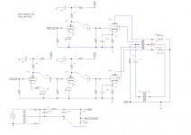
In addition to everyones suggestions,
I added a 22k unbypassed cathode resistor to the inverting triode.
This brought the gain of the stage down to 1.
(It was only being used to invert a single channel for the Matrix topology)
Cleaned up the hum in both channels") .
.
Included an updated schematic, as the original one had some component value errors + the cathode fix.
In addition to everyones suggestions,
I added a 22k unbypassed cathode resistor to the inverting triode.
This brought the gain of the stage down to 1.
(It was only being used to invert a single channel for the Matrix topology)
Cleaned up the hum in both channels
.Included an updated schematic, as the original one had some component value errors + the cathode fix.
Attachments
Last edited:
- Status
- This old topic is closed. If you want to reopen this topic, contact a moderator using the "Report Post" button.
- Home
- Amplifiers
- Tubes / Valves
- Buzz/Hum in Matrix amplifier