Not sure if this is the right place to post this but as the result of anything learned form this question will eventually end up in a line level xo it's here.
In definitions of the L-R 4th order circuit it's usually stated simply that it's the result of 2 second order Butterworth circuits in series. But both in schematics and the results of many of the online calculators the values of the first series/parallel combination are of different values than the second pair and they are also not always different by the same ratio. I haven't yet found any reference to what that's about. Can somebody give an introductory explanation to how this would be worked out?
Thanks
I assume you're talking about about line-level active circuits?
If so, two identical 2nd-order circuits (in series) with Butterworth alignment will indeed yield a Linkwitz-Riley 4th-order result.
Look here for the basics of this configuration:
Active Filters
Dave.
If so, two identical 2nd-order circuits (in series) with Butterworth alignment will indeed yield a Linkwitz-Riley 4th-order result.
Look here for the basics of this configuration:
Active Filters
Dave.
Hi and thanks.
In this case the question is about the passive filter.
I took another look at some calculators (four of them) and found they all agreed so I'll consider the one I found the other day that gave different values from the others as an exception, mistaken or not.
My point is that in written explanations of the L-R 4th order it's simply stated that it's two Butterworths in series but there's never a mention of the change in values between the first pair and the second. My question is about that. Just trying to understand what is being done.
Attachments
I don't know about Linkwitz-Riley, but perhaps to reduce possible confusion I could say:
1. Butterworth is not a circuit but a frequency response (maximally flat). A second-order Butterworth response can be had from active or passive circuits with the appropriate component values. In the case of a passive LC circuit the response depends on the exact resistive loading.
2. Directly connect two LC circuits and they will interact. This means that joining two passive 'Butterworths' is not the same thing as multiplying the individual responses of the two LC sections. (Two Butterworth active filters could be coupled and the outcome will be the same as multiplying the individual responses).
Hi DF,
OK thanks, I get what you say and that it's a response and that different values of R to C or L to C can net the same response at different impedances.
My question is about how and why the math is done the way it is shared by all the online calculators I've seen today. All online written descriptions for the non-engineer I've read say simply that two second order Butterworths in series net a fourth order L-R circuit. None of those descriptions touch on the detail as to why those two Butterworth circuits need to be different.
I'm not an engineer with the commensurate math knowledge (yet) so looking at Siegfried Linkwitz' web site is not helpful. I am however interested finding an explanation I am able to follow as a first step in understanding how to work it out myself.
The components in the first and second filter are different to improve the Q of the circuit.
If you simply use same components you will lose gain.
LR is also in phase between the low and high pass filters.
Also the response matches between the low and high pass filters.
All in all an excellent circuit.
If you simply use same components you will lose gain.
LR is also in phase between the low and high pass filters.
Also the response matches between the low and high pass filters.
All in all an excellent circuit.
Hi,
LR4 is two B2 in series electrically. That is actively you can
cascade two identitical B2 circuits, but that is not the only
way of cascading two circuits to end up with LR4, there
are degrees of freedom in 4th order implementations.
A passive LR4 (assuming a resistive load and zero source
impedance) can never be made by cascading two identical
B2's. It simply doesn't work like that. And it simply doesn't
work the way those stupid calculators calculate either.
(I've forgotten how to calculate passive higher order filter circuits,
so I can't tell you the standard theory stuff the calculators use.)
What you want is LR4 acoustic (not electrical). That is the
drivers responses follow LR4 in the x/o region via the x/o.
The x/o function needed has nothing to do with filter types.
(Its what you want acoustic minus the driver responses.)
e.g. : Zaph|Audio - ZA-SR71 , study this carefully.
The assymetry in the LR4 helps compensating driver offset.
rgds, sreten.
Last edited:
Thanks Nigel, that's answering my question. Can you recommend a place to look for a neophyte's understanding of how the math is arrived at for the specific values the calculators are getting?
Sreten,
Thanks! I get what you're saying that the calculators can't do anything re: the actual drivers' response. But it interests me that all of them are arriving at the same values. So, unless one guy wrote a speadsheet and everybody else on the web simply copied it, they must be looking at a certain idea with regard to doing the calculation. This was my question.
Anyway, I'll read the ZaphAudio page. Thanks for posting it.
In an active LR4 implementation, you have two B2 blocks, each with high input impedance and low output impedance. They do not interact. This is called a cascade.
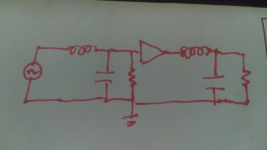
In a passive implementation, you have two LC circuits and the driver. It might be instructive to place yourself between the two circuits. The first circuit sees then the combined impedance of the driver and the second circuit. The second circuit sees the combined frequency response and output impedance of the amp plus the first circuit. these interactions are what cause the altered values.
If you don't know the math I can't get any more specific than that.
In the image, if you were to terminate the first circuit with a resistance same as driver and input into a new amp, the LC values would be the same in both circuits...make sense or does it make it murkier?
Attachments
Last edited:
try the Linkwitz Lab site - also has a crossovers page
and you did say you wanted to do this line level - active or passive?
and you did say you wanted to do this line level - active or passive?
Ron,
I don't know the math but your description gives me a perspective I can use to look for more answers. Thanks!
Add: No the image doesn't make it murkier but clarifies what you'd said. The next step for me is to learn how to work it. Though I don't know the math, I'm not averse to learning it. Math together with detailed description is what I hope for but am not likely to find.So it has to be pieced together a web-page at a time.
JCX,
The Linkwitz site is a little too mathematically thick for me at the present stage. All weight and no forward momentum gets me mired down without knowing what to ask. From my perspective a one step at a time Linkwitz page for dummies tutorial would be a plus.
My thought is to start experimenting with a passive between two (shunt cascode) buffer and output stages (because I already have the needed parts for, and some successful experience with, the circuit).
A passive filter requires both the source impedance and the load impedance to be fixed before the design can commence.Hi DF,
OK thanks, I get what you say and that it's a response and that different values of R to C or L to C can net the same response at different impedances.
My question is about how and why the math is done the way it is shared by all the online calculators I've seen today. All online written descriptions for the non-engineer I've read say simply that two second order Butterworths in series net a fourth order L-R circuit. None of those descriptions touch on the detail as to why those two Butterworth circuits need to be different.
I'm not an engineer with the commensurate math knowledge (yet) so looking at Siegfried Linkwitz' web site is not helpful. I am however interested finding an explanation I am able to follow as a first step in understanding how to work it out myself.
Usually the design assumes that the source impedance is zero ohms and the load impedance is infinite ohms. Those are the fundamental "rules" for that filter design.
If either the source impedance or the load impedance or both are not the same as the design assumptions, then the filter will not meet it's required roll-off characteristic.
Take a properly designed LC, or CL, filter that is exactly correct for the two terminal impedances and attach it to another identical filter and both filters will now be "wrong".
The first filter sees the second as it's load. It now has a different roll-off.
The second filter sees the first filter as it's source. It too is now corrupted.
Ron said much the same
In a passive implementation, you have two LC circuits and the driver. It might be instructive to place yourself between the two circuits. The first circuit sees then the combined impedance of the driver and the second circuit. The second circuit sees the combined frequency response and output impedance of the amp plus the first circuit. these interactions are what cause the altered values.
The desired cascaded LR4 does not work as intended because the two "Butterworth 2pole" are both corrupted.
Presumably the LR4 calculator takes account of the changed source and loading and give the correct component values to achieve a real LR4.
The mathematics (not simple arithmetic) is quite advanced to achieve a passive LR4.
I wonder if all the calculators give the same answers?
Last edited:
Before you can understand 4-th order filter synthesis you first need to understand 2nd-order filter synthesis - active and passive, and the difference between them. To start with you need to understand first order filters. Maths is unavoidable, so if you don't have the necessary background all you can do is accept what others say.
The Wikipedia page on L-R filters tells me that is is a filter with -6dB at the corner frequency. So 2nd-order L-R is a second order filter with Q=0.5. Fourth order L-R (the most popular) consists of two identical (frequency response) Butterworth (i.e. Q=0.707) second-order filters. Note that this assumes they are buffered (or active).
Two active filters (e.g. Sallen-Key) can be cascaded and you get the product of the individual responses. Two passive filters cannot be cascaded without affecting each other. Two solutions: use a buffer between them, or adjust the values.
There are various ways of adjusting the values so it is perhaps not too surprising that different calculators get different answers - however, I have not looked into this so I don't know if there is a range of correct answers or merely a range of useful approximate answers. My guess (and its only a guess) is that simply cascading two LC with no buffer cannot give the correct response, but can get sufficiently close for most practical purposes.
I wonder if all the calculators give the same answers?
All but one of the six or so I've tried. I looked again yesterday but was unable to find the exception. They all ask for load impedance and frequency. My guess is that source impedance is assumed to be zero or some generally accepted figure.
For a passive loudspeaker crossover assuming a zero source impedance would be a reasonable approximation.
I wonder if all the calculators give the same answers?
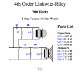
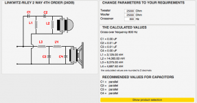
Actually , for the record, I was wrong. I looked again tonight and found three that give near but differing values.
(The 25000Ω was done thinking of the passive filter going into a grid circuit impedance.)
Attachments
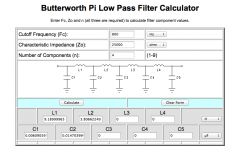
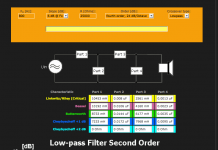
I think the first is not giving an LR4. It is titled Butterworth.
It also has C1 in there which is effectively doing nothing when the source impedance is zero, i.e. it leaves just three components forming an LCL filter
The third is titled "Low-pass Filter Second Order". That would make the top line components into an LR2, not an LR4.
It also has C1 in there which is effectively doing nothing when the source impedance is zero, i.e. it leaves just three components forming an LCL filter
The third is titled "Low-pass Filter Second Order". That would make the top line components into an LR2, not an LR4.
Last edited:
I suspect that the first and third also assume 25k source impedance, as well as 25k load impedance. The title on the third one is clearly wrong, as it shows 4th-order filters.
If you understand filters then you can successfully use an online calculator to do the hard work of doing the messy maths. Otherwise, they are likely to lead you astray.
If you understand filters then you can successfully use an online calculator to do the hard work of doing the messy maths. Otherwise, they are likely to lead you astray.
- Status
- Not open for further replies.
- Home
- Source & Line
- Analog Line Level
- Butterworth series to Linkwitz-Riley Calculation