Hello,
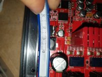
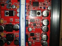
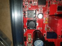
I need to replace the inductors for the Burson Soloist 3XP. One is marked "4R7", which is 4.7 µH. And 6 are marked "100" which is 10µH, it think. They measure about 11mmx11mmx8mm. The pcb pad space they are mounted to is slighty larger about 12.5mm.
Can I replace them with ANY SMD inductors with the same 4.7 µH and 10 µH and roughly the same dimensions??? Such as Coilcraft or Bourns or Wurth Elektronik:
https://www.digikey.com/en/products...e3X8PUWN72dZA27SLyf0Kx4OXDxdOBrxoCoi4QAvD_BwE
https://www.digikey.com/en/products...e3X8PUWN72dZA27SLyf0Kx4OXDxdOBrxoCoi4QAvD_BwE
I am completely new to this DIYaudio so I'm still learning. My multimeter did not maintain a proper voltage level when testing the inductors but other components seemed to be ok...
The amp died when I left it on and i think it overheated (after I modified the opamps to Sparkos SS2590 and left the cover off and had a cardboard box sitting over it, heat dissipation problem Im guessing). The power button is lit when plugged in but the amp does not turn on when pressing the button. However the amp did work perfectly with the sparkos ss2590 for the first 5-6 hour listen, but then I left it on the next day for 8-10 hours, thats when the problem began.
Any advice is greatly appreciated. Thank you.
Attachments

Why do you think the inductors need replacing?
You need to know the current rating, not just the inductance, to be sure a replacement will do, or just pick the highest spec'd devices of that inductance and size.
You need to know the current rating, not just the inductance, to be sure a replacement will do, or just pick the highest spec'd devices of that inductance and size.
No idea what you mean by this - could you elaborate how you measured and what you measured?My multimeter did not maintain a proper voltage level when testing the inductors
That could explain why it cooked - the covers are the heatsinks and require free-air convection to work, the box would prevent convection - I suspect it runs hot anyway in that small enclosure.and left the cover off and had a cardboard box sitting over it
Thank you for the reply.
https://www.digikey.com/en/products...e3X8PUWN72dZA27SLyf0Kx4OXDxdOBrxoCoi4QAvD_BwE
https://www.digikey.com/en/products...e3X8PUWN72dZA27SLyf0Kx4OXDxdOBrxoCoi4QAvD_BwE
Why do you think the inductors need replacing?
I used a basic multimeter and set it to "Diode testing mode". I connected the red probe to one side of inductor/pcb contact and the black probe to the other inductor/pcb contact point. The reading jumps up to a three digit number and immediately falls to a "0" along with a beeping sound. With my limited and basic research, a proper inductor should not fall to a "0" value. Correct? It should hold/maintain a certain value above "0". The beeping sound I'm not sure if that is a normal for an inductor or if that is a signal for a "short" as in mosfet testing. My mosfets maintain their numbers without any beeping alerts during the "Diode testing mode".No idea what you mean by this - could you elaborate how you measured and what you measured?
Ok. So, if indeed the inductors need replacing, minimum dimensions should be 11mmx11mmx8mm and the highest amp rating possible, which for now is 5.6 amps with DC Resistance (DCR) 21mOhm Max for the Wurth Elektronik and 4 amps with DC Resistance (DCR) 24.3mOhm Max for the Coilcraft. I'm unfamiliar with "DCR" numbers and need to learn more about it.You need to know the current rating, not just the inductance, to be sure a replacement will do, or just pick the highest spec'd devices of that inductance and size.
https://www.digikey.com/en/products...e3X8PUWN72dZA27SLyf0Kx4OXDxdOBrxoCoi4QAvD_BwE
https://www.digikey.com/en/products...e3X8PUWN72dZA27SLyf0Kx4OXDxdOBrxoCoi4QAvD_BwE
These are power inductors, not diodes, use resistance mode and check they have a low value, probably < 0.1 ohm.
Ok thanks for clarifying. That makes sense and they do appear to be testing ok.These are power inductors, not diodes, use resistance mode and check they have a low value, probably < 0.1 ohm.
Now, for the diode test, I did test the SMD Capacitors and got wildly irregular readings. When setting my multimeter to "diode test mode" and connected the multimeter positive lead to the positive contact point of on capacitor and the negative lead to the negative point of the capacitor, I got a steady rising number and eventually the multimeter reading settles on a specific number. BUT on other capacitors, the number quickly rises up up up and ends in a "1". I guessing these smd capacitors need to be replaced? The readings are not consistent on all of them, I think maybe half of all the capacitors need to be replaced, if that is what I'm discovering. If indeed the Burson Soloist amp overheated then the SMD capacitors would be the most sensitive to excessive heat, not the inductors or the mosfets, I'm guessing. Its going to be alot of work replacing those capacitors.

Maybe forget about the diode test mode for now.
https://en.m.wikipedia.org/wiki/Diode
Inductors and capacitors will have a very low failure rate in a situation like this.
I have no specific experience with this device, but it may have circuits to prevent damage to headphones if significant DC voltage is present.
So unless you have knowledge enough to effectively test around this, you probably won’t be able to see much.
Last edited:
Hi @Stereo101 , I'd like to know how you came to this conclusion.I need to replace the inductors for the Burson Soloist 3XP.
I'm not an expert technician (and not even a technician), but I'd like to know it anyway. 🙂
However, since I was intrigued by this thread, I deepened a bit the matter and learned the following:
"Companies is famous for encouraging "opamp rolling" meaning replacing a pair of op-amps with discrete ones. To have a baseline, I went to the non-glamorous JRC5532. Owner had shipped this with Sparkos and Vivid op-amps. What was supposed to be an easy process was a nightmare. The supplied sockets have large round holes that are too large for the flat pins of the JRC (and Vivid as owner told me). You have to mess with the pins to get them to insert while putting enough side pressure to the pins. If you don't do this, you get partial connection and an unhappy unit. Despite my best effort that took some half hour, I still don't like the results. If you are going to provide replaceability you better make sure the job is doable.
Swapping the opamps requires resetting DC offset using the 4 pots that are undocumented. Google search indicated such a functionality. I found one channel close to zero but the other with 45 mv of DC offset. I adjusted both channels to near zero.
Back to power, during the testing the unit got quite warm. Those output transistors dissipate a ton of power which they push into bottom of the unit. They must run very hot in order for the top to get warm as well.".
https://www.audiosciencereview.com/...urson-soloist-3xp-review-headphone-amp.34353/
So my question now is: have you done the above in detail?
And again, could it simply be the op-amps that are not well mounted and the DC offset not well adjusted instead? 🤔
I've been looking for an expert technician for advice and guidance but nobody is interested in working on the amp.Who told you to test in-circuit capacitors with a a diode tester? All your guesses are just nonsense.
Ok, sounds like this really can't be a diy fix. Also, technicians I've spoken to are also apprehensive to work on this device: unfamiliar with the device, don't want to be liable for it, too complicated etc..... So I've been on my own.Maybe forget about the diode test mode for now.
https://en.m.wikipedia.org/wiki/Diode
Inductors and capacitors will have a very low failure rate in a situation like this.
I have no specific experience with this device, but it may have circuits to prevent damage to headphones if significant DC voltage is present.
So unless you have knowledge enough to effectively test around this, you probably won’t be able to see much.
My conclusion was wrong and the inductors are fine. Also, like you I have not technical training in electronics. So for now I'm just treating this as a learning experience.Hi @Stereo101 , I'd like to know how you came to this conclusion.
I'm not an expert technician (and not even a technician), but I'd like to know it anyway.
Thank you for researching and pointing this out. That is interesting to learn and also reading the comments from audiosciencereview.com members regarding a circuit design that requires a DC offset, many don't seem to like it.Swapping the opamps requires resetting DC offset using the 4 pots that are undocumented. Google search indicated such a functionality. I found one channel close to zero but the other with 45 mv of DC offset. I adjusted both channels to near zero.
I'll look into adjusting the DC offset but this may require special measurement tools that I do not have. However, when the unit was working and I first installed the Sparkos SS2590 opamps, the amp worked perfectly for the 5 hours that I used it. The problem began when I took the metal cover off, placed a cradboard box over it and left it on for the entire day. Mark Tillotson explained that the cover acts as a heatsink and the box would prevent free-air convection. I do not know if the DC offset is connected to this problem.
I did read this in the ASR Burson thread and comments on how problematic the DC offset is and also the heat of the unit:
"I owned a soloist 3xp for a month or so, ergonomics (menues) was awful, sluggish volume control, dc-offset was impossible to zero out - it continues to drift when you put the cover back on due to further heating up. And on top of it all it lacks output protection.
That means for instance that if one of those fancy homebrew op-amps fail (or if you try out some exotic OPs that goes into oscillation), you could be injecting a large ammount of dc/ ultrasonic crap in your precious headphones. This is a bad design indeed.
I sold it as soon as I realized how crappy it was. Now I have an HPA4, and it has volume acceleration, no offset problems, and dc-protection, I would call that a keeper."
See, my reply was inspired by the fact that you had reached a technical conclusion despite not having the related technical expertise by your own admission.
So I thought I would also give you an address towards other people's experiences which are often constructive, especially considering the fact that no owner of the same device has (yet) replied here.
Anyway, the fact that you have covered an appliance that heats up a lot and left it running with a box denotes a certain technical ingenuity that requires awareness in order to add a significant element to your personal wealth of experience.
However, I didn't understand if you only covered the upper part of the device or if you just inserted it entirely inside a box without any vents, I'd like to see a photo of it.
IF the device were mine I would roll the standard op-amps again to see if the exchange offers any positive innovations even simply at the level of electrical contacts and I would check the integrity of each existing fuse (if any).
I would also suggest reading the following thread which I think is very informative in some posts
https://www.head-fi.org/threads/bur...-with-muse72320-volume-control.941047/page-53
Extrema ratio, but not that much, send an enthusiastic e-mail to Burson Audio (infoATbursonaudio.com) replacing AT with @ and I'm sure they will respond appropriately and quickly on the best thing to do in your case, just like what happened to me recently for a completely different issue.
Thanks for the reply and taking the time to send me links. Getting the technical feedback from this forum it seems like the cost and effort to repair the device exceeds my novice skill level and the actually worth of amp and better to apply the money towards a new device. Right now I want to build my own amp and develop my soldering skills. So this non working amp will become a learning experience in diagnostics work and circuit design. I have much to learn.
Thanks again.
Good question. The box was actually a box cover, the kind you find in candy or chocolate boxes, about 2 or 3 inches deep. My intent was to use the box as a dust cover. So with the metal cover off, the cardboard box sat elevated above PCB on top of the rear input panel and front volume control panel. On the left and right sides there was about a 1 inch gap between the box and the PCB. So I thought there would be enough air flow. The box sat "on top of" and not "around" the device. The width of the box were slightly narrower than the Soloist.However, I didn't understand if you only covered the upper part of the device or if you just inserted it entirely inside a box without any vents, I'd like to see a photo of it.
I tried but to no success. With fuses I can only see one fuse at the power input but maybe there are others on the PCB...IF the device were mine I would roll the standard op-amps again to see if the exchange offers any positive innovations even simply at the level of electrical contacts and I would check the integrity of each existing fuse (if any).
Will do. My device was bought used and out of warranty but still worth a shot.Extrema ratio, but not that much, send an enthusiastic e-mail to Burson Audio (infoATbursonaudio.com) replacing AT with @ and I'm sure they will respond appropriately and quickly on the best thing to do in your case, just like what happened to me recently for a completely different issue.
Thanks again.
Okay, so it might not even have been the box cover, considering that we are not in summer and the ambient temperature, especially at night, should not (hopefully) be "high" at all and that it is the entire cabinet that is the heatsink (even considering that for sure the top plate matters) and the transistors are placed to the bottom plate.The box was actually a box cover
Let's be clear, what @Mark Tillotson told you is absolutely probable and since the amplifier is Class A it certainly heats up a lot, but it could also have been a coincidence or the amplifier could (should?) also have some sort of protection to prevent irreparable damage that we ignore.
At Burson Audio they know it for sure of course and you will see that they will answer you, they only have to gain by doing so. 😉
Please don't forget to also include the serial number of the amp, don't say that you bought it used and be enthusiastic about how it sounds.
👍 Welcome to the rabbit hole.Right now I want to build my own amp and develop my soldering skills.
Last edited:
Yes, here (it may not even be related at all with overheating, so fingers crossed).maybe there are others on the PCB...
- Home
- Amplifiers
- Headphone Systems
- Burson Soloist 3XP Inductors