Hello all, this is my first post at diyAudio. 😉 I've known the forum for a long time, but never joined until now. I'm sure I will learn a lot of things here. 😀
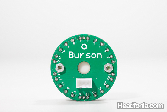
I'm just curious, and would like to know if it's possible to use the Burson attenuator on regular amplifiers. The attenuator only come with 3-pins (L, R, G), and according to Burson, it's specifically designed that way for installation with their amplifiers.
Here is a picture of the attenuator installed in their headphone amplifier, the HA-160:
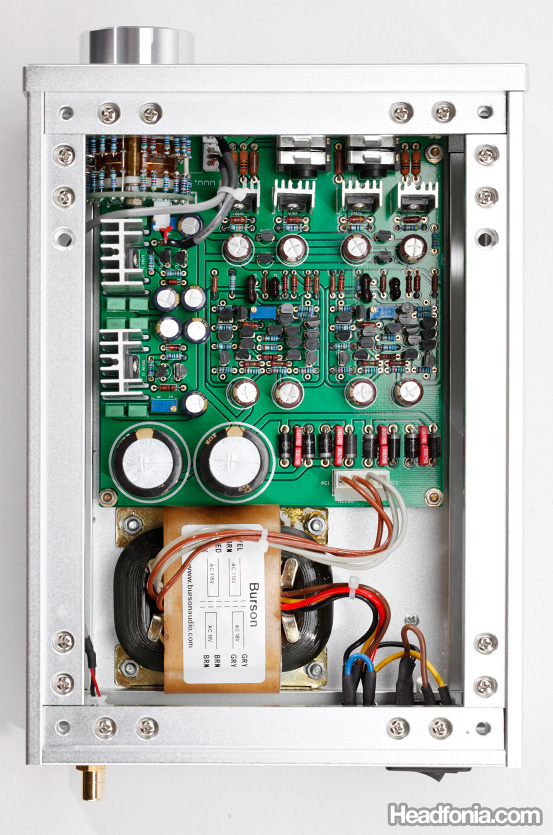
It's not really evident in that photo, but the line goes from the RCA inputs to a 3-pins connector on the PCB marked INPUT. From the PCB there is a 3-pin connector marked VOLUME that goes to the 3-pins on the attenuator.
My friend suggested that the resistors on the right side of the attenuator may be run in series with the attenuator, and that the attenuator is basically a variable resistor. But I still don't get how the thing works to attenuate the signal.
I'm just curious, and would like to know if it's possible to use the Burson attenuator on regular amplifiers. The attenuator only come with 3-pins (L, R, G), and according to Burson, it's specifically designed that way for installation with their amplifiers.
Here is a picture of the attenuator installed in their headphone amplifier, the HA-160:
It's not really evident in that photo, but the line goes from the RCA inputs to a 3-pins connector on the PCB marked INPUT. From the PCB there is a 3-pin connector marked VOLUME that goes to the 3-pins on the attenuator.
My friend suggested that the resistors on the right side of the attenuator may be run in series with the attenuator, and that the attenuator is basically a variable resistor. But I still don't get how the thing works to attenuate the signal.
If it is a var resistor it works by connecting a resistor after the series resistor to gnd. That attenuates the signal, right?
So when you switch different resistors to gnd you can control volume.
The downside is that the resistance seen by the source varies with volume, and at min volume it is only the series resistor. So the source must be able to drive that series resistor value as load.
jd
So when you switch different resistors to gnd you can control volume.
The downside is that the resistance seen by the source varies with volume, and at min volume it is only the series resistor. So the source must be able to drive that series resistor value as load.
jd
Hi Janneman,
Yes, I get what you mean. But still I'm not very clear on how to implement this on a circuit that's designed to be used with regular 6-pin attenuators?
Yes, I get what you mean. But still I'm not very clear on how to implement this on a circuit that's designed to be used with regular 6-pin attenuators?
I'm wondering if this would be correct:
Line in --> R1 (some large resistance, 50K-100KOhms) -->
--> Amplifier Input
--> Attenuator
Line in --> R1 (some large resistance, 50K-100KOhms) -->
--> Amplifier Input
--> Attenuator
I'm wondering if this would be correct:
Line in --> R1 (some large resistance, 50K-100KOhms) -->
--> Amplifier Input
--> Attenuator
Assuming this stereo atten has three pins, one would be the gnd pin for both channels (probably the middle pin 😉 ), and a 'hot' pin for each of the channels. What you do is use a series R from input jack to amp input. Then you connect a 'hot' pin to the series R at the side of the amp input, for each channel, and the gnd pin to, ehhh, gnd.
You can try it out, you can't break anything.
One issue is the value of the series R; that should be in the Burson specs. If you can't find it, start with 10k. If the level is too low, you can decrease it down to a couple of k. Again, you can't break anything so just do some R&D😉
jd
Thanks. I managed to get it to work, exactly by adding a serial resistor. I happened to have 10K ohms laying around, so I used that and it works great. 😀
- Status
- Not open for further replies.