OK I'm making two sets of OP Amps for an input to a ADC and output from an DAC. I dont think I've over soldered them and i checked it many times before I powered them. The design I've used is the recomended from the datashhets of the ADC and the DAC, but they are getting extreamly hot. I rewired and tested a few of the seperate amp with a simple closed loop gain circuit and some of them have burnt out  . I tryed simulating the design in multisim but its giving me errors. Take a look at my design, I'm not sure what I've done wrong
  .
.
DAC: http://www.ortodoxism.ro/datasheets/texasinstruments/pcm1730.pdf
ADC: http://focus.ti.com/lit/ds/symlink/pcm1804.pdf
OPAMP: http://www.selectronic.fr/includes_selectronic/pdf/Burr-Brown/OPA134_2134_4134.pdf
Thanks.
. I tryed simulating the design in multisim but its giving me errors. Take a look at my design, I'm not sure what I've done wrong .DAC: http://www.ortodoxism.ro/datasheets/texasinstruments/pcm1730.pdf
ADC: http://focus.ti.com/lit/ds/symlink/pcm1804.pdf
OPAMP: http://www.selectronic.fr/includes_selectronic/pdf/Burr-Brown/OPA134_2134_4134.pdf
Thanks.
Attachments
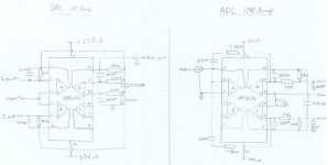
The filter section (DAC part) is wired incorrectly. Take a closer look at Fig.7 in the DS and compare with what you have.
ADC is also wrong: You need a buffer/follower (1st OP), then an inverter (2nd OP), and both outputs of the buffer and the inverter feed their corresponding filter section (3rd and 4th OP), see DS Fig.44.
And, quite important: You must not leave opamps unconnected. Wire them as followers (OUT to -IN) and connect the input (+IN) to GND. Otherwise the might oscillate.
Do you have adequate power supply bypassing right at the chip?
- Klaus
I see what you mean. I don't know what I had drawn, must have got really mixed up somewhere. Also, would those incorrections have caused permanant dammage to the packages? The power supply i used was +/-12V connected correctly. I used a 25W iron with a 1mm tip, didnt take too long to solder, but for a few pins I had to apply about 6 seconds of heat to get the packages held down. I dont think that could have caused problems though.
KSTR said:Do you have adequate power supply bypassing right at the chip?
- Klaus
You never answered Klaus in regards to your supply bypassing. This could be an issue.
- Status
- This old topic is closed. If you want to reopen this topic, contact a moderator using the "Report Post" button.
- Home
- Amplifiers
- Chip Amps
- Burnt my finger - OPA4134