... lots of support & info for these MOSFETs in other arenas here at the Pass Labs Support Forums (diyAudio.com). But you knew that already ...  ... I'll look at mine later for model/part numbers ... but I believe if memory serves I have the lower power sets.
... I'll look at mine later for model/part numbers ... but I believe if memory serves I have the lower power sets. I had decided not to take home anything after last years haul...
but a winning raffle ticket convinced me otherwise.
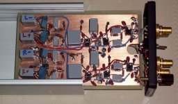
I made it home with a beautiful chassis stuffed with 6 complementary pairs per side (with 4 sets on one pcb and two sets on another). It also features a 40-0-40 trafo. I was instructed by Nelson to wire it for 240V operation giving a nominal 20-0-20, rectified to 28-0-28. Then build a nice little class a amp.
Thank You Nelson!
I am open to any suggestions on how to best utilize this wonderful stuff.
My speakers consist of two JBL 2226H woofers per side topped with JBL 2435H compression drivers on Edgar tractrix horns. These are currently driven by a mini-Aleph with regulated supplies for the horns and a Hafler XL280 drives the woofers. A Marchand XM1 splits the signal at 800 Hz.
I am fascinated by the idea of a First Watt B4 preamp driving step-up transformers into First Watt F4 amps. The B4 would replace the XM1 crossover and include boost to correct the low frequency roll off from the high efficiency woofers.
I suppose a current source amp could take care of the LF response without using EQ.
Any thoughts? What should I build?
best regards,
psz.
but a winning raffle ticket convinced me otherwise.
I made it home with a beautiful chassis stuffed with 6 complementary pairs per side (with 4 sets on one pcb and two sets on another). It also features a 40-0-40 trafo. I was instructed by Nelson to wire it for 240V operation giving a nominal 20-0-20, rectified to 28-0-28. Then build a nice little class a amp.
Thank You Nelson!
I am open to any suggestions on how to best utilize this wonderful stuff.
My speakers consist of two JBL 2226H woofers per side topped with JBL 2435H compression drivers on Edgar tractrix horns. These are currently driven by a mini-Aleph with regulated supplies for the horns and a Hafler XL280 drives the woofers. A Marchand XM1 splits the signal at 800 Hz.
I am fascinated by the idea of a First Watt B4 preamp driving step-up transformers into First Watt F4 amps. The B4 would replace the XM1 crossover and include boost to correct the low frequency roll off from the high efficiency woofers.
I suppose a current source amp could take care of the LF response without using EQ.
Any thoughts? What should I build?
best regards,
psz.
Looking in the chassis I am curious as to where people are going to mount the input stage and power supply. Everything else fits in there so nicely, but I can't figure out where the original design for these amps would have placed those boards.
One of the really cool things about those chassis is that they all came equipped with top notch Vampire RCA input connectors and output binding posts, and what looked like Neutrik XLR's, plus fuse posts and AC inlets - all brand new!
I think someone needs to calculate the number of square inches of heatsink area and make an estimate of how much heat can be dissipated. That will dictate how much power can be expected from the output section. Maybe Nelson has that info.
Graeme
I think someone needs to calculate the number of square inches of heatsink area and make an estimate of how much heat can be dissipated. That will dictate how much power can be expected from the output section. Maybe Nelson has that info.
Graeme
Without having taken a side panel with the board and mosfets off,
I haven't figured out where you would solder in the driver and output
connections, but I would be inclined to mount perfboard/pcbs on the
rear surface with standoffs up far enough to be away from the AC
plumbing.
I haven't figured out where you would solder in the driver and output
connections, but I would be inclined to mount perfboard/pcbs on the
rear surface with standoffs up far enough to be away from the AC
plumbing.
So I'm starting this thread to get a couple of designs together that can be put together easily. I figure that some F4 type follower systems will be the easiest, although there's no reason that we can't explore other stuff.
I've always wanted to hang some output followers on a BZLS. Maybe that will end up being one of the other things explored?
JJ
The chassis and parts were originally made to form test beds for
playing around with designs. I think it will be useful to continue
that approach.
Those concerned that the power supply voltages are too high will
find that a 240V input configuration will take care of that.
As far as front ends go, there are a lot of possibilities, but for starters
a nice follower configuration will form several interesting possibilities
for push-pull and single-ended class A designs.
Some of you are emailing me with regard to these things, but I think
it will be more useful and efficient to air questions and answers
publicly. You will be directed to this thread.
Also, I counsel patience. There are a lot of possibilities on the table,
and it will take time to work through them.
Also, a number of you out there (and you know who you are )
)
will be making your own contributions to this, and these will be
most welcome.

playing around with designs. I think it will be useful to continue
that approach.
Those concerned that the power supply voltages are too high will
find that a 240V input configuration will take care of that.
As far as front ends go, there are a lot of possibilities, but for starters
a nice follower configuration will form several interesting possibilities
for push-pull and single-ended class A designs.
Some of you are emailing me with regard to these things, but I think
it will be more useful and efficient to air questions and answers
publicly. You will be directed to this thread.
Also, I counsel patience. There are a lot of possibilities on the table,
and it will take time to work through them.
Also, a number of you out there (and you know who you are
) will be making your own contributions to this, and these will be
most welcome.
Nelson Pass said:
Also, a number of you out there (and you know who you are
will be making your own contributions to this, and these will be
most welcome.
My contribution. . . ?
It might be becoming a quiet observer. . .
Cheers,
🙂
Burning Amps At The Ready
Hi All,
I was so disappointed that I couldn't make the festival again this year. But my mood over missing another year was lifted last night when a generous friend decided I should do something with amps 28 and 35. Now my mind is reeling.
What I know so far is that one has BJTs and the other MOSFETs. One has a transformer and one does not. No driver boards on either. I won't have time to look deeper until next week.
My thinking is that I may want to convert the BJT to MOSFET based solely on my positive experiences with MOSFET designs. Then I would set them as monoblocks though I wonder if the damping factor of 20 at 100W is low. Still need to read the F4 OM in detail though I skimmed it this morning.
I've got loads a of questions and plan to be patient and see what appears on this thread. Any specific guidance would be greatly appreciated.
Nelson, your generosity is staggering. Thank you.
kurt
" ... No driver boards on either. ..."
I don't believe any of these chassis from the BA 'Fest have the low level pre-amp / controller boards ... or wiring ... Many do have the mounted output boards that hold the drive transistors (& MOSFETs) and most have transformers and caps and I/O connectors and power switches ... which is all I wanted for my pet project.
Wondering if Pass Labs will allow us to purchase the appropriate transformers, pre-amp boards, etc. that may be required to finish these ... 😕
I also notice that mine is equipped with a lot of silver (or silver plated) wiring from the I/O connections. 😉
My intention is to install a pair of these:
http://aussieamplifiers.com/nx150.htm
The ones I have are equipped with balanced inputs, so the XLR connections in the chassis I got will work out nicely. (I also have pairs of 400 and 500 watt modules that I will want to test and measure, thus the requests for the higher voltage xformers.) ... 😎
I don't believe any of these chassis from the BA 'Fest have the low level pre-amp / controller boards ... or wiring ... Many do have the mounted output boards that hold the drive transistors (& MOSFETs) and most have transformers and caps and I/O connectors and power switches ... which is all I wanted for my pet project.
Wondering if Pass Labs will allow us to purchase the appropriate transformers, pre-amp boards, etc. that may be required to finish these ... 😕
I also notice that mine is equipped with a lot of silver (or silver plated) wiring from the I/O connections. 😉
My intention is to install a pair of these:
An externally hosted image should be here but it was not working when we last tested it.
http://aussieamplifiers.com/nx150.htm
The ones I have are equipped with balanced inputs, so the XLR connections in the chassis I got will work out nicely. (I also have pairs of 400 and 500 watt modules that I will want to test and measure, thus the requests for the higher voltage xformers.) ... 😎
jacco vermeulen said:Geez, next thing you know the big guy will come over to your kitchen table.
your or mine ?

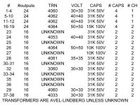
So here's the list I have of the amplifiers, keyed to the number on
the amp. If you lost that piece of paper, you will find the number
on the floor of the amp on a Dymo label.
The list is not 100% accurate.
If the devices on the amp are *ALL* IRF240 or IRF244 or IRF230 then
you have what we will call SE for single-ended.
If they are a mix of IRF240, etc and IRF9240 or other "9" types, then
you have what we will call COMP for complementary
If they are MJ part #'s, then they are BIPOLAR.
Attachments
I won the first doorprize, which was two amps or a pair of RAAL ribbons. I have the last speakers I'll ever own, and I think it wrong to sell a gift/prize, so I took the amps. I can't design an amplifier, so any shortcut advice to get me where I want to go will be appreciated. But I can solder, cut metal, and troubleshoot pretty well. My last project was a dead-bug build of Joe Curcio's phono preamp in National's appnote 1651 using the LME49710 opamp (photo attached).
My speakers need five amps each, around 60 watts. I'd like to use the amp with 24 N-channel IRF240 mosfets (#18 on Nelson's list) to make a four- or six-channel amp, and the amp with 12 IRF744/IRF9240 (#17) pairs to make a four channel amp.
Both amps have the AVEL 4064 transformer, 50-0-50 secondaries, 530VA. This should give 60-65 volt rails if hooked up for 120VAC. The mosfets can handle 11A or 18A at 200V, so I think they could handle any supply based on this tranny.
So what to do? I'm not familiar with Nelson's stuff (though I had an Aleph 30 here once) and would like to try his class A designs. The Aleph J is class A push-pull running at 24V rails using four mosfets. It's rated at 25 watts. At 50% efficiency in class A, I should be able to get four 60 watt channels idling at 60 watts (120wpc 4 = 480, 530VA power tranny) or six channels at 45 wpc music, 90wpc total per channel.
Before going further down this path, could the Aleph J driver be altered to drive the mosfets at these levels? Would the distortion be so high that this is a bad choice?
Thanks,
- Eric
PS - I'd probably build the drivers dead-bug style to get the density necessary to fit six complete driver circuits into the amp.
Attachments
Eric Weitzman said:My speakers need five amps each, around 60 watts. I'd like to use the amp with 24 N-channel IRF240 mosfets (#18 on Nelson's list) to make a four- or six-channel amp, and the amp with 12 IRF744/IRF9240 (#17) pairs to make a four channel amp.
So you are quint-amping the speakers. What drivers are you using in them?
Nelson Pass said:So you are quint-amping the speakers. What drivers are you using in them?
Two 10" Peerless XLS woofers 830452, one Seas 8" Excel midrange W22EX01, and two Seas Excel Millenium 1" dome tweeters T25CF002 (one rear firing). These are Linkwitz Orion speakers. The tweeters can be run in series on one amp channel if it doesn't mind the low impedance.
If this all worked out, it would be sweet to swap amp side panels and make two 5-channel amps. Your modular chassis design makes this possible. Each box would have both amp types in it!
- Eric
Mine was one of the 30s, I forget which.
Unknown transformer turned out to be 80+96 with a center tap. I also have a 330VA 25+25 on hand. That should be good for +/35 or +/-17 volt rails.
Outputs are comp bipolar, but I also took home a bag of the n-channel mosfets Nelson was handing out. Or I can buy additional parts as necessary, of course.
My power needs are modest, I'm currently running a Trends TA-10 that puts out about 6 watts/channel. My speakers are 95dB efficient Hawthorne drivers in open baffles.
Eric, I think your project is intrigeing as I have always wondered specifically what the Orions would sound like with some Pass amps. Somehow it just seems that it might work very well..
In fact I had proposed that Seigfried Linkwitz bring his Orions and then I was going to suggest to Nelson that he bring some amps to power them.. You know, the old "hollywood" method -get one guy and the pitch t he idea to the other.
Linkwitz didn't go for it so I guess you will have to show up next year with your rig!
There is room for 2 stacked transformers in the box so you could even have different voltages. If you run the transformers at 220v input, your rails would be around a bit lower than 35v I believe- would work with some Pass designs.. (Aleph?) I think that the F4 needs to be no more than 30v rails:
http://www.diyaudio.com/forums/showthread.php?postid=1638033#post1638033
Stock is about 22v rails I believe
but maybe some pretty hefty resisitors in the pi filter would lower the voltage?
Nelson: Your chart for #26 is wrong ... xformer should be 18+18 (Avel model AT7 D4030).
But that's OK. I'll just get a bigger one for my project = no worry, mate.
But that's OK. I'll just get a bigger one for my project = no worry, mate.
Cotswold Electronics Transformer
FWIW, #28, a Comp MOSFET unit, and has no transformer thought the spreadsheet indicated that it was a 4061.
#35, a bipolar unit, with transformer indicated as unknown, has a 45+45 transformer from Cotswold Electronics Model D1054. I can't seem to find any info on this one at all despite multiple searches of every combination I can think of.
Have a great evening!
- Status
- Not open for further replies.
- Home
- Amplifiers
- Pass Labs
- Burning Amps