
Towers. So increased bias doesn't increase linearity. Why does it have the affect of decreasing distortion in many cases?
Greetings,put small caps on output of dcb1 and see if that helps.
This is my first post. I have been reading/learning here for a while, but didn't have anything to contribute until now.
I built a hard wired version of the BA-2, and experienced a brief turn-off noise from the amp. I took a look at the outputs with my scope, and found that there was a very high frequency oscillation transient causing the sound. After some puzzling over the problem, on a hunch I moved the gate stopper resistors, connecting them directly to the mosfet gate leads. They had been connected to the gates via about 1.5 inches of wire. This completely solved the problem. The amp had shown no instability while powered up. I later noticed that Papa mentioned that mosfets can make very good oscillators with just a short length of hook up wire on their gates. I don't know if this happening with your amp, Yap BC, but it might be.
Thanks Papa. You are a great teacher!
Hi,
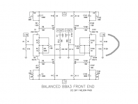
Am i correct that i would need two BA3 boards for a stereo Balanced BA3? If i also want inbalanced inputs, is there way to implement it?
Am i correct that i would need two BA3 boards for a stereo Balanced BA3? If i also want inbalanced inputs, is there way to implement it?
yes, and yes
how to do it balanced have been shown
but not how to wire the single ended to balanced input
I would surely like to see it too
how to do it balanced have been shown
but not how to wire the single ended to balanced input
I would surely like to see it too
Turn-off noise
I am using a BA-2 board purchased from DiyAudio Store. I supposed that the components' placement and tracks' length on the board would have been optimized to prevent oscillation.
Since I do not have a scope, I just used some trial and error methods to rectify it. I guessed that the main power supply switch in my amp could have contributed to the problem during turn-off, so I just added some X2 capacitors with a total value of 0.1 microfarad to the power on-off switch to improve on the suppression during turn-off. No more turn-off noise. Even occasionally when it happens, the turn-off noise is very much reduced. Anyway, thanks for your suggestion.
Greetings,
This is my first post. I have been reading/learning here for a while, but didn't have anything to contribute until now.
I built a hard wired version of the BA-2, and experienced a brief turn-off noise from the amp. I took a look at the outputs with my scope, and found that there was a very high frequency oscillation transient causing the sound. After some puzzling over the problem, on a hunch I moved the gate stopper resistors, connecting them directly to the mosfet gate leads. They had been connected to the gates via about 1.5 inches of wire. This completely solved the problem. The amp had shown no instability while powered up. I later noticed that Papa mentioned that mosfets can make very good oscillators with just a short length of hook up wire on their gates. I don't know if this happening with your amp, Yap BC, but it might be.
Thanks Papa. You are a great teacher!
I am using a BA-2 board purchased from DiyAudio Store. I supposed that the components' placement and tracks' length on the board would have been optimized to prevent oscillation.
Since I do not have a scope, I just used some trial and error methods to rectify it. I guessed that the main power supply switch in my amp could have contributed to the problem during turn-off, so I just added some X2 capacitors with a total value of 0.1 microfarad to the power on-off switch to improve on the suppression during turn-off. No more turn-off noise. Even occasionally when it happens, the turn-off noise is very much reduced. Anyway, thanks for your suggestion.
wrong guess , except if you deliberately want mute function 
for unbalanced input , just ground neg input
RCA hot to +in , RCA gnd to gnd
for unbalanced input , just ground neg input
RCA hot to +in , RCA gnd to gnd

Attachments

So, I've been trying to keep up with this thread but, I have a question I don't remember anyone discussing.
What cap is everyone using for C1 & C2? I don't find many "Audiophile" types that fit the footprint of the DiyAudio store board? It needs to be 13mm or less Dia. The B.O.M. specifies 1000u 25V but no mfg, model etc.etc. I'm not sure how low a voltage you can go there but, under normal conditions 10V or 16V would be safe? Gotta think about that somemore?
Any comments? Suggestions? Thanks 😀
I used Elna 50v. WAY too big. Cant remember if they have smaller varities. Also tried Nichicon, but didnt notice a lot of difference. I am considering smaller Elnas or cerafine for final build.
Yes, I have 1000u 50V silmics and their a littlle big for the board. I do have a 2200 25V Rubycon Low ESR (Black Gate mfg'r) that almost fits. I also have a few 470 in Silmic and Cerafine @ 16V I may try???
😕
😕
Last edited:
What cap is everyone using for C1 & C2? I don't find many "Audiophile" types that fit the footprint of the DiyAudio store board?
its in series with power supply
why would you need it to better than the supply caps 😕
I will use the new compact brown Panasonic FR type
105 degr, long life, high ripple current, low ESR
what else counts 😕
its in series with power supply
why would you need it to better than the supply caps 😕
The power supply, under certain conditions, may apppear totally across one component. What might that be 50V??? I don't see an expected condition where that might happen with C1 & C2 in this circuit though. But, all those unexpected things are hard to imagine. We ussually think of normal operation, and not necessarily start-up or shut down or hi-cup on-off behaviour etc. etc.???
I will use the new compact brown Panasonic FR type
105 degr, long life, high ripple current, low ESR
what else counts 😕
Well, ESL is also important but, when it comes to caps, some people think they hear all kinds of stuff that's wrong but, sometimes no stuff, depending on the cap, the dialectric etc. I'm not sayin anything new here. But, we want that cap to be totally inert as it deals with the input signal as a short to Power supply, AC gnd. In other words, the cap is invisible to AC and imparts no non-linearities on the F.E. signal being passed to the output FETs. 1000uF is only available in electrolytic, which have a questionable audiophile performance. However, there is a Silmic looking cap in N.P.'s pic of his board. What's that cap???
Last edited:
....... as it deals with the input signal as a short to Power supply, AC gnd.
its in paralel with bias pot, which is basicly a resistor
wouldnt the pot 'take over' 😕
There is a Silmic II Elna cap that is 16 MM diameter 1000uF 25 volts. Digikey P/N is 604-1059-ND.
The signal's current variation see's the 100 ohm and then the C||500 pot. But, the C||Pot has the Xc of the cap dominating. Probably equal to a 250 pot at 2Hz. Above 2 Hz it's impeadance is a closer to a short cicuit to the power supply. But it blocks the DC needed to help bias the ouput FETs. That DC is added to the 100 ohm DC drop to form the output stage bias. Adjust the 500 ohm pot controls the DC but at audio freq.s does nothing (we hope).
- Home
- Amplifiers
- Pass Labs
- Burning Amp BA-3