Hi,
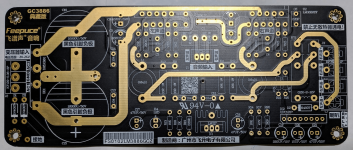
I've just built an LM3886 kit and it's all good when test outside the case. The odd happen when I put in the case. The big resistor was almost burnt. What happen?
I don't have circuit diagram but I traced the PCB and the almost-burnt resistor are in Zobel network (R9, R11). I was able to repeat the problem when connect input wire and when I checked, the input signal ground was shorted to the chassis (I didn't connect any source). Speaker wires are open circuit when this happen.
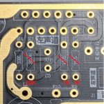
Another thing I didn't do prior to this is that I've omitted C3, C4 which seems to be negative feedback network. This PCB use 33pF and 220k resistor in parallel. Would this be the reason for open circuit oscillation?? Is it even oscillation? The capacitor was left out because one local builder suggest that he felt it's restricted the treble response of the amp.
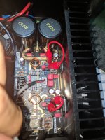
So, I fixed this by redoing the input signal connector and ensure that input ground is isolated from the chassis. I also soldered C3, C4 in. I left the almost-burnt resistors in since they are still measured good at 10 ohms. The amp is working good now for few hours, but still curious what was the cause.
Any thoughts?
AP
I've just built an LM3886 kit and it's all good when test outside the case. The odd happen when I put in the case. The big resistor was almost burnt. What happen?
I don't have circuit diagram but I traced the PCB and the almost-burnt resistor are in Zobel network (R9, R11). I was able to repeat the problem when connect input wire and when I checked, the input signal ground was shorted to the chassis (I didn't connect any source). Speaker wires are open circuit when this happen.
Another thing I didn't do prior to this is that I've omitted C3, C4 which seems to be negative feedback network. This PCB use 33pF and 220k resistor in parallel. Would this be the reason for open circuit oscillation?? Is it even oscillation? The capacitor was left out because one local builder suggest that he felt it's restricted the treble response of the amp.
So, I fixed this by redoing the input signal connector and ensure that input ground is isolated from the chassis. I also soldered C3, C4 in. I left the almost-burnt resistors in since they are still measured good at 10 ohms. The amp is working good now for few hours, but still curious what was the cause.
Any thoughts?
AP
Attachments
It's not unusual for the Zobel resistor to burn up when there is oscillation or high power testing.
Normally it is necessary to float the input sockets from the chassis to avoid problems.
Normally it is necessary to float the input sockets from the chassis to avoid problems.
Oscillation can definitely blow up Zobel network resistors and those capacitors are probably meant to improve stability.
If the zobel resistors are burning out, it suggests the amplifier is oscillating. Perhaps some of the capacitors you omitted were to prevent this?
Thanks. I've read the 3886 datasheet and the capacitor seems to be the position of "Cf" which is done to reduce HF gain (Figure 3, p6).
https://www.ti.com/lit/ds/symlink/lm3886.pdf
What do you think of the value chosen for this PCB? Is it optimal for sound? I'm not sure how to calculate since my PCB employs slightly different configuration.
https://www.ti.com/lit/ds/symlink/lm3886.pdf
What do you think of the value chosen for this PCB? Is it optimal for sound? I'm not sure how to calculate since my PCB employs slightly different configuration.
The values of the feedback and gain-setting resistors are much too high -- and that's one of the reasons it's oscillating. The other is the poor layout. Use the values in the TI datasheet.What do you think of the value chosen for this PCB? Is it optimal for sound? I'm not sure how to calculate since my PCB employs slightly different configuration.
See the attached -- it may help. Would also suggest lifting one leg of the 33pF capacitors and placing 20k in series. This will smooth the transition to lower gain at higher frequencies.
Before TI bought Nat Semi, the latter's datasheet suggested bypassing the power supply rails with 10uF and 100nF ceramic.
It is NOT a good layout, however. Had the designer read the datasheet they would have been warned that these chipamps are susceptible to oscillation if lead-lengths are not kept as short as possible.
Attachments

I'll definitely try that. Not sure why the gain is set that way. I must say I'm impressed with the sound even at current setting and poor layout. It's my first chip amp build,See the attached -- it may help. Would also suggest lifting one leg of the 33pF capacitors and placing 20k in series. This will smooth the transition to lower gain at higher frequencies.
Before TI bought Nat Semi, the latter's datasheet suggested bypassing the power supply rails with 10uF and 100nF ceramic.
It is NOT a good layout, however. Had the designer read the datasheet they would have been warned that these chipamps are susceptible to oscillation if lead-lengths are not kept as short as possible.
back to oscillation!See the attached -- it may help. Would also suggest lifting one leg of the 33pF capacitors and placing 20k in series. This will smooth the transition to lower gain at higher frequencies.
Before TI bought Nat Semi, the latter's datasheet suggested bypassing the power supply rails with 10uF and 100nF ceramic.
It is NOT a good layout, however. Had the designer read the datasheet they would have been warned that these chipamps are susceptible to oscillation if lead-lengths are not kept as short as possible.
I've changed the value of resistors per recommendation, however, the problem is opposite now. It oscillates (zobel resistor heats up, too hot to touch) when open circuit at input! The oscillation is gone when I connect source and play some music.
Any thoughts? I've also replace zobel resistor to 2W so they can take more beating.
Attachments

Normally I would put at least a resistor to ground and a passive RC low-pass filter at the input. Is there something like that on your PCB?
Would be helpful to see the schematic.Normally I would put at least a resistor to ground and a passive RC low-pass filter at the input. Is there something like that on your PCB?
@tempoct -- does it oscillate with the inputs shorted? does it oscillate with the output connected to a dummy load?
Read again pages 20 and 21 of the datasheet.
Last edited:
Thanks. It doesn't oscillate when input shorted. It's still quietly oscillating when test speakers connected.Would be helpful to see the schematic.
@tempoct -- does it oscillate with the inputs shorted? does it oscillate with the output connected to a dummy load?
Read again pages 20 and 21 of the datasheet.
However, when I bypassed the 20k resistor that in series with 33pF, the oscillation is gone. I'm trying to reverse engineer the pcb for schematic now.
Attachments

I never understood what the idea behind C7 is, but with a much increased impedance of the feedback network compared to the circuits in the datasheet, the pole it causes is bound to reduce the phase margin compared to what the National Semiconductor people had in mind. Leaving the input open will aggravate this.
What happens when you either:
connect 220 pF between pin 10 and ground and nothing between pins 10 and 9,
or reduce it to 33 pF between pins 10 and 9 and connect 220 pF from pin 10 to ground,
or change everything according to the datasheet application circuits?
What happens when you either:
connect 220 pF between pin 10 and ground and nothing between pins 10 and 9,
or reduce it to 33 pF between pins 10 and 9 and connect 220 pF from pin 10 to ground,
or change everything according to the datasheet application circuits?

I guess it already has a path to ground, that it is just missing from the reverse-engineered schematic, otherwise it shouldn't work at all.
Hi tempoct
Your LM3886TF is unstable. That's the reason your zobel resistor is burnt.
My LM3886TF is working perfectly.
I've attached my schematic for your reference.
It shows you the important parts of the circuit, particularly the negative feedback network.
Regards
Mike
AmpsLab

Your LM3886TF is unstable. That's the reason your zobel resistor is burnt.
My LM3886TF is working perfectly.
I've attached my schematic for your reference.
It shows you the important parts of the circuit, particularly the negative feedback network.
Regards
Mike
AmpsLab
Why u need 27k at the negative rail?Hi tempoct
Your LM3886TF is unstable. That's the reason your zobel resistor is burnt.
My LM3886TF is working perfectly.
I've attached my schematic for your reference.
It shows you the important parts of the circuit, particularly the negative feedback network.
Regards
Mike
AmpsLab
View attachment 1068645
You should have 0.1-1.0 uF X7R ceramic or film capacitor from V+ and V- to ground right at the IC power pins. Without those the LM3886 tends to oscillate. See here for more information: https://neurochrome.com/pages/supply-decoupling
Is pin 5 (V+) of the IC not connected? It should connect to V+ (most commonly at pin 1).
As Jack has pointed out you need a DC path to ground from both IN+ and IN- on the LM3886 (or any other opamp) for it to land at a stable DC operating point.
Tom
Is pin 5 (V+) of the IC not connected? It should connect to V+ (most commonly at pin 1).
As Jack has pointed out you need a DC path to ground from both IN+ and IN- on the LM3886 (or any other opamp) for it to land at a stable DC operating point.
Tom
- Home
- Amplifiers
- Chip Amps
- Burn(t) resistor at the output stage LM3886TF, please help analyze...