
Hi i am working on Burmeister 933 MK2 clone,
There is a 500 ohm TRIMMER on each channel and i do not know what are they used for? Can anyone have an idea and correct position of trimmer?
It's R17 on the schematic, used for bias setting.
The procedure is the following:
1) Before the first power on - set R17 to zero (shorted) position.
2) Connect the voltmeter (some 200mV scale) - one lead to the top of R37, the other lead to the bottom of R38.
3) Power on. You should see something from zero to few mV. If you see more than 200mV - better power off, something is wrong.
4) Turn R17 carefully, until you set 65mV there - this will give you around 70mA of quiescent current through the output pair.
5) As soon as the output pair on a heatsink will warm-up, the voltage you see will slip away slowly - just correct it back to 65mV - carefully, no fast moves. It will settle completely in 20-30 minutes. Then you're done.
Cheers,
Valery
Wow Thanks for Quick response, 65mV is common value or you calculate according to my amplifier layout?
Where you get this pcb?Hi i am working on Burmeister 933 MK2 clone,
There is a 500 ohm TRIMMER on each channel and i do not know what are they used for? Can anyone have an idea and correct position of trimmer?
Wow Thanks for Quick response, 65mV is common value or you calculate according to my amplifier layout?
I don't know the exact designer's recommendation for the quiescent current for this particular circuit, but something around 70mA (which is 65mV across the resistors in your case) is good enough for most of the output stages of this kind.
Cheers,
Valery
Where you get this pcb?
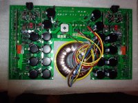
i order from china via agent. That picture is dummy. Mine is here below still on progress.
Attachments

- Status
- Not open for further replies.