Re: We have awfull enclosures here...and cost a fortune.
Olá Carlos !
Nice to meet you ! Good to see some fellows from Brazil around. I followed some of your posts - you are incredibly funny !😀 I have been in Recife once when I was little - I will try to come back !
Ah...Gradiente. Great company, beautiful story (not so beautiful now) ... They made excellent equipment a long time ago. I have a model 900 at home, incredible sound (even more incredible if you consider it uses 2 pairs of MJE 3055 at the output).
The circuit you sent is from which model ? do you know ?
Thank you very much for your tips !! I am seriously considering using properly MDF. Like you said: chassis here cost a lot and look awful ! Right now my AMP is sitting on top of a piece of wood waiting for my dad to knock it down when he tries to turn on the Cd player. 🙄
Abraços !
João Pedro
destroyer X said:Very nice your presence.
Attaching a very good Gradiente Amplifier....hehe...maybe JVC.
I use to put some 10 ohms to start ground.... this will be my input ground....only to input.
I am doing cases with MDF....easy to make them...but too much dirty it makes inside one appartment.
I am in Recife, my home town is Rio, Copacabana is the place.
Carlos Eugênio
Olá Carlos !
Nice to meet you ! Good to see some fellows from Brazil around. I followed some of your posts - you are incredibly funny !😀 I have been in Recife once when I was little - I will try to come back !
destroyer X said:Attaching a very good Gradiente Amplifier....hehe...maybe JVC.
[/B]
Ah...Gradiente. Great company, beautiful story (not so beautiful now) ...
They made excellent equipment a long time ago. I have a model 900 at home, incredible sound (even more incredible if you consider it uses 2 pairs of MJE 3055 at the output). The circuit you sent is from which model ? do you know ?
destroyer X said:So, good to try your own, using your own "taste" related size and shape.
regards,
Carlos
Thank you very much for your tips !! I am seriously considering using properly MDF. Like you said: chassis here cost a lot and look awful ! Right now my AMP is sitting on top of a piece of wood waiting for my dad to knock it down when he tries to turn on the Cd player. 🙄
Abraços !
João Pedro
Well João Pedro, i am missing those amplifier that appear when i was young
STR1050, model 80, model 120, model 160, Lab45, lab90.
Have you some schematic?... i am crazy to construct one circuit just to remember.
Use electrolitic condenser...ahahahah...2200uF to speaker coupling...BD239/140.....RCA 2N3055 in the output....very interesting Museum schematic.... and i am searching, and cannot find to construct and heard again.
It is a good reference..... some old reference.... to see how amplifiers are better now (are they?)
Having some schematic, please João....send me as soon as possible.
Thank you, because apreciate my posts....you are very kind.
nanabrother@yahoo.com
regards,
Carlos
Input coupling capacitors (again)
Hi K-amps,
Sorry, I think I didn't express myself clearly. Currently, I don't have a loudness circuit. I just mentioned it beacuse I thought the lack of it may explain the not too strong bass response of my amp at low volumes. In fact, does anyone know a good Loudness circuit easy to implement (without the use of a potentiometer with loudness tap) ??
I agree with you that electrolytics are not a good idea in input coupling. But with such low input impedance (around 10k) a 5uF wouldn't be too low value ?
I thought the following way, considering a low frequency of 10 Hz
Xc = 1 / (2*Pi*5uF*10Hz) = 3183 ohm
Considering an input resistor of 10 K at the differential input (which mainly determines the input impedance) I would have
Vbase = voltage at input of diff amp.
Vin = voltage of signal
| Vbase | = Rin ^ 2 / Sqrt(Rin ^ 2 + Xc^2) * |Vin|
| Vbase | = 0.30 * |Vin| (too much attenuation)
Did I get it right ? Maybe I should increase Rin...
Thanks for the help,
João Pedro
K-amps said:With variables as significant as loudness circuits, I doubt the lytics are causing this... however you should be ok with a nice PIO (paper in Oil) or Metallized Polypropylene of 2uF-5uF or so. (50-63v). Electros sound terrible...
Hi K-amps,
Sorry, I think I didn't express myself clearly. Currently, I don't have a loudness circuit. I just mentioned it beacuse I thought the lack of it may explain the not too strong bass response of my amp at low volumes. In fact, does anyone know a good Loudness circuit easy to implement (without the use of a potentiometer with loudness tap) ??
I agree with you that electrolytics are not a good idea in input coupling. But with such low input impedance (around 10k) a 5uF wouldn't be too low value ?
I thought the following way, considering a low frequency of 10 Hz
Xc = 1 / (2*Pi*5uF*10Hz) = 3183 ohm
Considering an input resistor of 10 K at the differential input (which mainly determines the input impedance) I would have
Vbase = voltage at input of diff amp.
Vin = voltage of signal
| Vbase | = Rin ^ 2 / Sqrt(Rin ^ 2 + Xc^2) * |Vin|
| Vbase | = 0.30 * |Vin| (too much attenuation)
Did I get it right ? Maybe I should increase Rin...
Thanks for the help,
João Pedro
A major manufacturer of one the most popular 200 wpc power amplifier specifies a 22k input impedance. They use a 1uF input coupling cap with a -0.25db 10Hz spec.
So even with a 2.2uF cap, (and 10k input impedance) you should be the same... going to 5uF will put you down at 4-5Hz....
I am no math major so I cannot verify you calcs. 😀
So even with a 2.2uF cap, (and 10k input impedance) you should be the same... going to 5uF will put you down at 4-5Hz....
I am no math major so I cannot verify you calcs. 😀
jpnascim said:I agree with you that electrolytics are not a good idea in input coupling. But with such low input impedance (around 10k) a 5uF wouldn't be too low value ?
With a 4.7uf input coupling cap, and 10k to ground you have a high-pass filter at 9.96Hz, which is fine.
And at 4.7uf you can use a good film cap.
Re: Input coupling capacitors (again)
 No, I am wrong ! There was a mistake in my formula. Doing math in the morning is bad.... Correct formula would be:
(still considering: Vbase = voltage at input of diff amp and Vin = voltage of signal )
| Vbase | = Rin / Sqrt(Rin ^ 2 + Xc^2) * |Vin|)
Which, would give me, for C=4.7uF and Rin = 10.000 kohm :
| Vbase | / |Vin| = 0.828
Expressing it in dB:
20 Log (| Vbase | / |Vin|) = -1,640 dB
I hope I am right this time... 😉
So, like K-Amps and Carlosfm stated, I should be fine at 10 Hz. Now I need to get film caps.
Thanks !
João Pedro
jpnascim said:
I thought the following way, considering a low frequency of 10 Hz
Xc = 1 / (2*Pi*5uF*10Hz) = 3183 ohm
Considering an input resistor of 10 K at the differential input (which mainly determines the input impedance) I would have
Vbase = voltage at input of diff amp.
Vin = voltage of signal
| Vbase | = Rin ^ 2 / Sqrt(Rin ^ 2 + Xc^2) * |Vin|
| Vbase | = 0.30 * |Vin| (too much attenuation)
Did I get it right ? Maybe I should increase Rin...
Thanks for the help,
João Pedro
No, I am wrong ! There was a mistake in my formula. Doing math in the morning is bad.... Correct formula would be:(still considering: Vbase = voltage at input of diff amp and Vin = voltage of signal )
| Vbase | = Rin / Sqrt(Rin ^ 2 + Xc^2) * |Vin|)
Which, would give me, for C=4.7uF and Rin = 10.000 kohm :
| Vbase | / |Vin| = 0.828
Expressing it in dB:
20 Log (| Vbase | / |Vin|) = -1,640 dB
I hope I am right this time... 😉
So, like K-Amps and Carlosfm stated, I should be fine at 10 Hz. Now I need to get film caps.
Thanks !
João Pedro
JPnascim...João Pedro, i have lost your mail..send me your mail please!
I could read it...but a problem here forces me to delete...to format all my HD.
So, i could not even answer you..
Kind message.
Please, put your mail adress in our forum profile...or send it to me please.
Yeah!...i wanna Gradiente schematics...YEAHHHHHH!
Carlos
I could read it...but a problem here forces me to delete...to format all my HD.
So, i could not even answer you..
Kind message.
Please, put your mail adress in our forum profile...or send it to me please.
Yeah!...i wanna Gradiente schematics...YEAHHHHHH!
Carlos
jpnascim said:
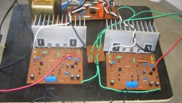
Unfortunately I don’t have a digital cam to send some pictures but I’ll try…
Well, after some months I've managed to obtain some pictures of this amp I've built. It continues to sound great.... 🙂
Sorry about the mess 😀 !
João Pedro
Attachments
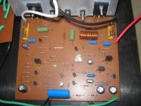
Your power supply caps look like they are too small.... small PSU caps can cause hum.... (Size is not always a good indicator of capacitance ut still they seem underrted.)
K-amps said:Your power supply caps look like they are too small.... small PSU caps can cause hum.... (Size is not always a good indicator of capacitance ut still they seem underrted.)
Hello K-amps,
The PSU capacitors are from SIEMENS, rated 50 V 10.000uF each. I don't have Slone book in my hands right now but I recall trying to follow one of his advices when rating caps for the PSU. I will recheck that. Do you think it is necessary to go for bigger caps ?
The amp is driving a pair of 8 ohm loudspeakers and show no signs of serious hum (just a little bit when no music is playing and you have to put your ears close to the loudspeaker).
Best regards,
João Pedro
hummmmmmmm..... ,a diy confidence killer

u know that a hummmmmm can reverbrate through the mind and heart of a diy person and shake of his resolve.y so?bec this irritating noise means imperfection in your work.
when i built my first amp,it was noisy like hell,reason being that it was built on a vero board.
so i took off from my computer to use cad program to draw a good layout and laid down the pcb tracks.
i took every concern concerned to make a good n great layout so that no noise can interfere.thick earth lines,zero jumps,thick wires for o/p and thin ones for i/p.
i assembelled that amp with all care and voila!!!on the first start the amp blasted out loudly to my happiness.it worked to great levels for a week or so but that !@#$% hmmmm appeared from nowhere.that made me doubt for a sec my ability to make a good board for myself!!but i made out that if it worked fine earlier then whats making it funk now??
i double checked all the solder joints to see if any is loose.best way is to see loose joints is use a continuty tester while pressing the components inside the pcb.if soldering will be loose then no continuty.
two three were loose. ifixed them and the humm was gone.
what i suppose in your case will be bec of leaky capacitors.check them through capacitance meter.
one very common reason is oscillations which can be due to micro mini ripples inherrent to any power supply output which are amplified by amplifier to give out that disgusting sound.
to avoid oscillations,use a 100nf capacitor(metal film) from each supply rail to ground as close as possible to the amplifier power i/p as possible.
keep track lenght microscopic from 100nf caps to the required semiconductor.this will surely take care of noise.one very common reason for noise but not yours is faulty pcb layout so if u design yours,do read guidlines for pcb design available at the site of EXPRESS PCB.
hope this essay helps..
Re: hummmmmmmm..... ,a diy confidence killer
Oh yes, since this is my first DIY amp I didn't expect to work 100 % at the first time. There are probably many imperfections in my work but I don't expect it to be 100 % perfect either ! 😀
I tried to be very, very careful with solder joints, I took my time, used a shinny lamp and went really slow, soldered, inspected, soldered, inspected
I don't have a cap meter to check if my electros are leaky, unfortunately. Well, I have a simple one in my digital multimeter but it goes up to 20 uF only. But I would like to do this check. I just don't know how...
Right. In my case, power supply is decoupled on the PCB board using 100 nF metallized polyester capacitors between V+ and GND, V- and GND. It is also decoupled in each amp board using, 100 nF and 220 uF capacitors between each rail and ground. I guess that is enough....
But anyway I appreciate your suggestions very much sagarverma. Next time I will do better following much of the advices posted by you guys.
Thank you very much
João PEdro
sagarverma said:
u know that a hummmmmm can reverbrate through the mind and heart of a diy person and shake of his resolve.y so?bec this irritating noise means imperfection in your work.
when i built my first amp,it was noisy like hell,reason being that it was built on a vero board.
Oh yes, since this is my first DIY amp I didn't expect to work 100 % at the first time. There are probably many imperfections in my work but I don't expect it to be 100 % perfect either ! 😀
The layout came with Slone book. Since I had no experience and hearing how painfull can be to get a good layout I decided to use that one. But there are some small problems with his layout regarding the star ground practice which I've tried to follow. It mixes feedback return, input signal and rail decoupling grounds. I found that strange and one thing I could do was to join input grounds with a thin wire and then run it to the star ground, just like schematics from my previous posts showed. It still has decoupling and feedback grounds mixed but considering the hum levels I have now I will just leave it alone and get it right in next amp ! 😉so i took off from my computer to use cad program to draw a good layout and laid down the pcb tracks.
i took every concern concerned to make a good n great layout so that no noise can interfere.thick earth lines,zero jumps,thick wires for o/p and thin ones for i/p.
i assembelled that amp with all care and voila!!!on the first start the amp blasted out loudly to my happiness.it worked to great levels for a week or so but that !@#$% hmmmm appeared from nowhere.that made me doubt for a sec my ability to make a good board for myself!!but i made out that if it worked fine earlier then whats making it funk now??
i double checked all the solder joints to see if any is loose.best way is to see loose joints is use a continuty tester while pressing the components inside the pcb.if soldering will be loose then no continuty.
two three were loose. ifixed them and the humm was gone.
what i suppose in your case will be bec of leaky capacitors.check them through capacitance meter.
I tried to be very, very careful with solder joints, I took my time, used a shinny lamp and went really slow, soldered, inspected, soldered, inspected
I don't have a cap meter to check if my electros are leaky, unfortunately. Well, I have a simple one in my digital multimeter but it goes up to 20 uF only. But I would like to do this check. I just don't know how...
one very common reason is oscillations which can be due to micro mini ripples inherrent to any power supply output which are amplified by amplifier to give out that disgusting sound.
to avoid oscillations,use a 100nf capacitor(metal film) from each supply rail to ground as close as possible to the amplifier power i/p as possible.
keep track lenght microscopic from 100nf caps to the required semiconductor.this will surely take care of noise.one very common reason for noise but not yours is faulty pcb layout so if u design yours,do read guidlines for pcb design available at the site of EXPRESS PCB.
hope this essay helps..
Right. In my case, power supply is decoupled on the PCB board using 100 nF metallized polyester capacitors between V+ and GND, V- and GND. It is also decoupled in each amp board using, 100 nF and 220 uF capacitors between each rail and ground. I guess that is enough....
But anyway I appreciate your suggestions very much sagarverma. Next time I will do better following much of the advices posted by you guys.
Thank you very much
João PEdro
Well folks,after 1 year...
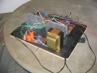
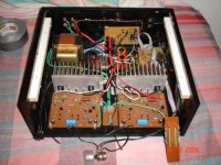
Hello everyone !
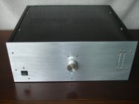
Almost after a year since my last post here I come back to post some pictures of my finished amp. I did the chassis by myself using plywood smoothed with acrylic mass and high quality glossy black paint. The reason is that it is really difficult to find companies that construct chassis projects out from a drawing at reasonable prices here.
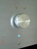
The panel is made from 5mm aluminum and it is my design also. The knob I've got from a repair shop and it is from an old vintage receiver, paid really cheap.
All its parts are screwed together firmly (i think more than 30 screws in totoal 😉 )
Well, it is far from perfect but I am satisfied with the results and feel great that I could get my first DIY project completed. the amp is playing great, hum is almost gone thanks to help from many here. Now I can sit back and listen to some good music ! 😀
I hope you like it !
Best regards,
João Pedro
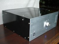
First picture, top view, without panel mounted.
Hello everyone !
Almost after a year since my last post here I come back to post some pictures of my finished amp. I did the chassis by myself using plywood smoothed with acrylic mass and high quality glossy black paint. The reason is that it is really difficult to find companies that construct chassis projects out from a drawing at reasonable prices here.
The panel is made from 5mm aluminum and it is my design also. The knob I've got from a repair shop and it is from an old vintage receiver, paid really cheap.
All its parts are screwed together firmly (i think more than 30 screws in totoal 😉 )
Well, it is far from perfect but I am satisfied with the results and feel great that I could get my first DIY project completed. the amp is playing great, hum is almost gone thanks to help from many here. Now I can sit back and listen to some good music ! 😀
I hope you like it !
Best regards,
João Pedro
First picture, top view, without panel mounted.
Attachments
- Status
- Not open for further replies.
- Home
- Amplifiers
- Solid State
- Built my first amp ! (Randy Slone Design 4) But it is humming...