Well after fighting with the LM3886 and parasitic oscillations, it blew up my SMPS on my test board.
so i fixed it, and decided out of curiousity, to pull out my discrete hybrid transistor/IC design, and it worked fine with my SMPS....
here is a video clip of the amp in operation:
http://pubserver1.ath.cx/MOV00483.mpg
also i have my rails regulated at about 32volts, but when i connect up the amp, it sags to 20v, thats idle current. it drops to 12 when i get it going and cranked up. in the video, i dont have it up that loud, so the rails right around 20v.
i think what has alot to do with it, i built the SMPS on a breadboard for testing, and all those long thin wires are playing a roll in stray inductance, and unwanted resistance enough so it cant draw enough current to keep the rails at 32v.
so im going to transfer it to a proto/veroboard, and tie the mosfets directly to the transformer without wires. just run the coil points streight to the drains.
any suggestions?
You need an oscilloscope to find out what is going wrong in the SMPS, but it's likely to be the regulation loop. You need a decent layout too, at least in the power path.
well i disabled regulation via software. ran full 50% duty. same issue.
im going to have to break out that huge a** scope. lol. i really need to invest in a handheld.
most likely my supply wires, and drive wires from the FETs to the transformer arnt large enough to supply the current required to really kick it in.
im going to have to break out that huge a** scope. lol. i really need to invest in a handheld.
most likely my supply wires, and drive wires from the FETs to the transformer arnt large enough to supply the current required to really kick it in.
im going to try an SG3525 controller instead of using my own PWM CPU with code and see what happens.
could be the way the PWM is driving the transformer. we'll see 🙂
could be the way the PWM is driving the transformer. we'll see 🙂
Hi
It is nice that you are working on your own project, but you could still for one that was olready build and tested, but I would like to see it done with CPU...
And how does people get chips like LM to oscillate? My didn't do that not once, don't see how that happens...
It is nice that you are working on your own project, but you could still for one that was olready build and tested, but I would like to see it done with CPU...
And how does people get chips like LM to oscillate? My didn't do that not once, don't see how that happens...
well i figured out what it was.
i used an SG3525 laying around, and i built that little circuit off to the side, and unhooked the drive wires from my AVR CPU to the SG chip, and boom. rails back to 42v or so unregualted.
that means the AVR isnt driving the mosfets correctly. then it just hit me.
the AVR chip is a 5V chip. that means the PWM ouput is 0-5-0v
i dont think 5V turns the fets on hard enough to draw a sufficiant amount of current to keep the rails up.
thats the problem. i put a couple of push-pull buffer transistors hooked to 12V, and it only raised it to 22v instead of 20v.
my next method is either use a CMOS buffer gate IC, or use a 339 comparator to boost up the drive to 12-0-12.
or do it like i did on my motor control servo, use a optoisolater between the fet and the AVR. that way if the fet blew, the AVR is protected. 🙂
as far as the LM chip, that probably was becuase my rails were so low. between 15 to 20v. that will cuase anything to oscillate.
because i unhooked the lm3886 amp, and hooked it up to my mains benchtop 35-0-35 supply, it works fine.
also is an LM3886 supposed to get warm at quiescent? because if i leave the 3886 hooked up with no signal, it will get slightly warm even though its not being driven. only thing i can figure is because its oscillating at a frequency that i dont hear.
yeap then its oscillating. thats the only thing i can figure. my discrete amp in the clip is happy as it can be. i dont get it...
Hi, mbates14
What core are you using? The safe bet is using ferrite (assuming your oscilation is below 50khz). If it is cracked, it will look like speaker's magnet material.
What core are you using? The safe bet is using ferrite (assuming your oscilation is below 50khz). If it is cracked, it will look like speaker's magnet material.
using a transformer pulled from a fried commercial amp. the output caps were rated 35V in the commercial amp, so maybe its only designed to run at 23 to 26V or so.
that means ill have to add more turns to the secondary. 😛
that means ill have to add more turns to the secondary. 😛
Dear mbates 14.
Succesful SMPS design follows three very strict rules: Layout, Ground planes, Very short wires and terminals.
You can't reliably make a SMPS to work on a protoboard. The keyword here is "reliably". Switching very high dI/dt waveforms with all that stray inductance and distributed capacitance and high-Z connections, will only cause voltage overshoots, ground bounce and signal crosstalk. Not to mention unecessary headaches for yourself.
Most semiconductor app-notes indicate that a double sided PWB is mandatory. However that is something that becomes very expensive very rapidly, as one debugs the circuit.
What I've done in the past with success is to use point to point wiring (with emphazis on short wires), on which I sandwich a blank copperclad board exclusively as a ground plane, and the high power busses I employ copper foil to carry the current. All the connections (at least the ones that carry any significant amount of current) must be soldered.
Let me see if I can find one of the old prototypes which I've built, to illustrate the technique.
you mean point-to-point wiring as in the old tube designs? but keeping everything close together?
Not exactly like the point to point wiring in tube designs, but in small perfboards, .
A picture is worth a thousand words...let me see if I can find something.
A picture is worth a thousand words...let me see if I can find something.
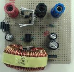
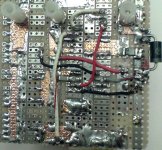
Please see attached images of a 12 v in, 24 v out @ 1 amp that a friend of mine built with my guidelines.
You can clearly see the straight and short wiring, and that conductors that carry high currents are beefed up with copper foil tape.
The supply is running at a relatively slow 50 Khz, so he could get away without a dedicated ground plane.
You can clearly see the straight and short wiring, and that conductors that carry high currents are beefed up with copper foil tape.
The supply is running at a relatively slow 50 Khz, so he could get away without a dedicated ground plane.
Attachments
to mbates14
Hi, mbates14 sorry for posting here but I don´t know how to contact you...
My question is about an infocus LP350 power supply failure, I read your post and follow your guidelines to repair some of them but one fail again, please reply to me:
http://www.diyaudio.com/forums/showthread.php?s=&postid=1358294
... repairing this type of power supply... definitively you are the man !
Please help me.
Thanks in advance.
- Status
- Not open for further replies.
- Home
- Amplifiers
- Power Supplies
- built a car amp, have an issue