This is a detailed wiki for volume controller group buy.
Due wiki limitation to 50 images, it was split into parts.
Part 2
[h=Bill of Materials]%1[/h]
BoM is available for download from below link.
https://docs.google.com/spreadsheet...HiIyZQHBxJVBQxT6wF42agyGZU/edit#gid=173448974
Please note that depending on firmware type some parts may not be used.
[h=Schematic and documentation]%1[/h]
Main website page http://vicol-audio.ro/volume-controller.php
Schematic -> http://www.diyaudio.com/forums/grou...volume-controller-4-inputs-5.html#post4109749
Connections -> http://vicol-audio.ro/img/volume-controller/wiring.png
Please note that trafo must be 6Vac @ min 1A.
[h=Assembly instructions]%1[/h]
To mount this KIT you need to use a very good soldering station. I suggest one of these:
Velleman VTSSC50NU or Hakko Digital FX888D
Make sure that you are using a anti-static ESD protected workbench. Any electrostatic discharge may destruct atmel or alter firmware.
Solder I use is http://www.tme.eu/en/details/sn96a-0.5_0.5/solders-wires/sn96a-0505#
If you prefer lead http://www.tme.eu/en/details/lc60-0.50_0.5/solders-wires/lc60-05005#
I'm using a lot of colophony (rosin), depending on your soldering stile you may need more or less.
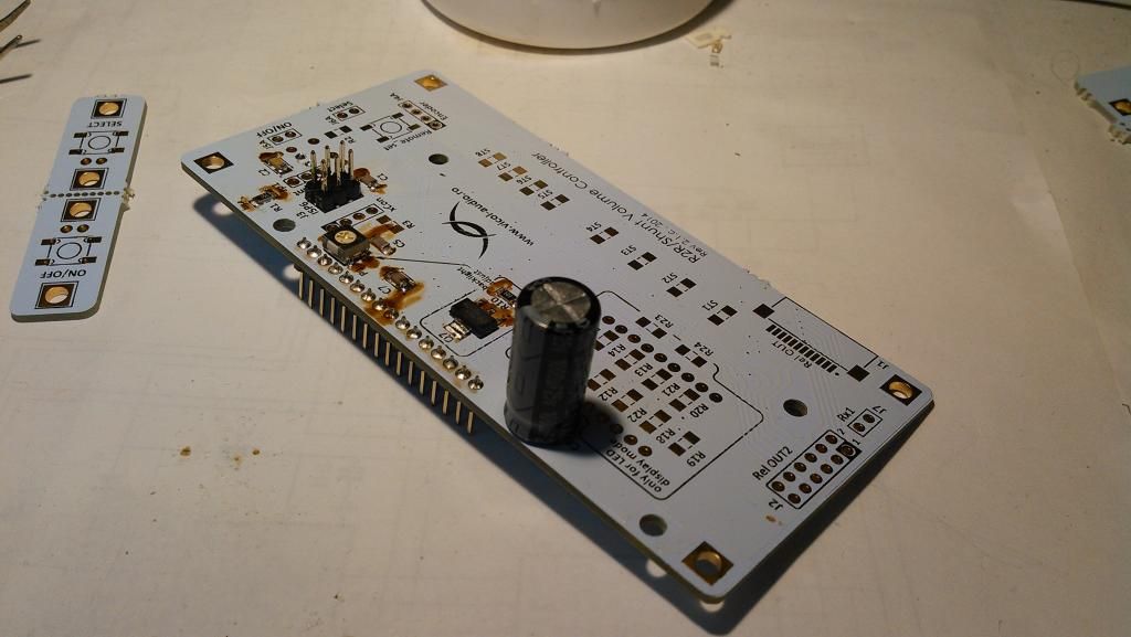
Display board
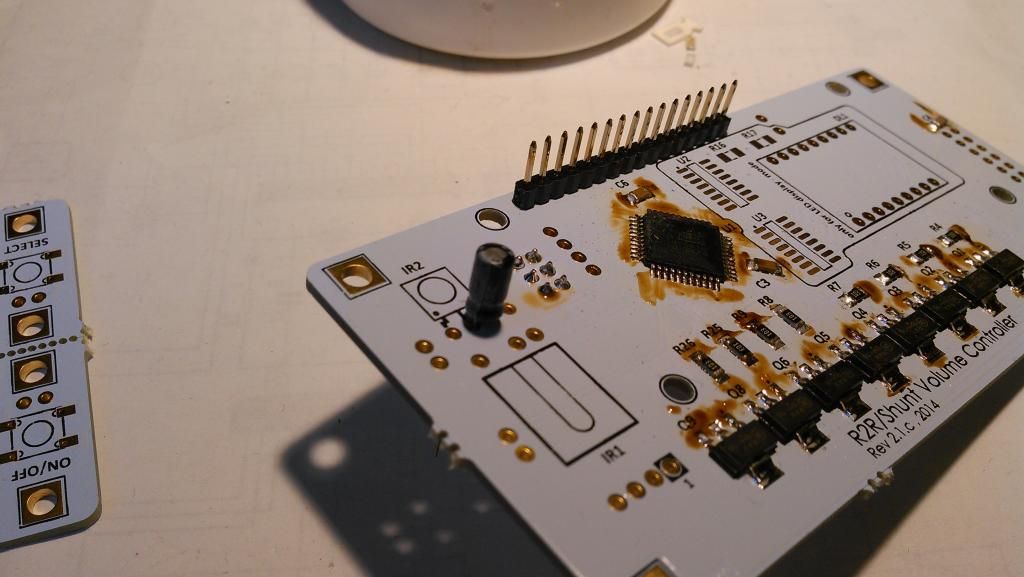
Start mounting by soldering Atmel microcontroller. First solder only one pin and when you have perfectly placed the IC over pads solder the rest.
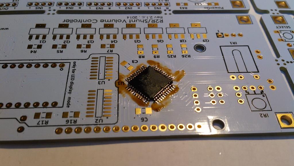
Don't hurry to clean the board, This will be done at the end using isopropyl alcohol.
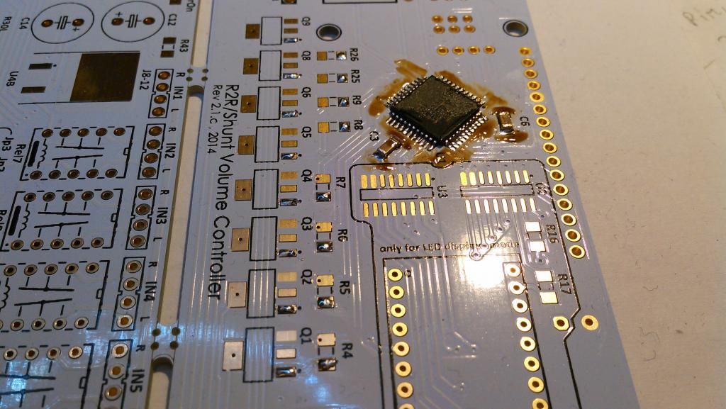
Now solder decoupling caps for microcontroller and prepare the board for transistor and resistor soldering - a very small drop of solder only on one side.
Align and solder all 10K resistors and BCP56-16 transistors.
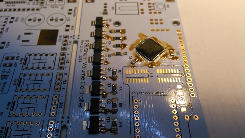
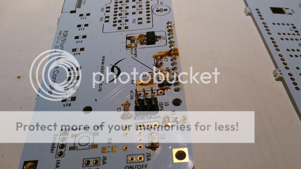
Finish the soldering after all parts are perfectly aligned.
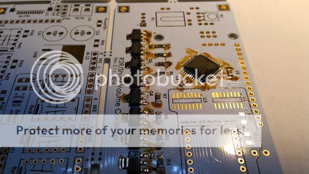
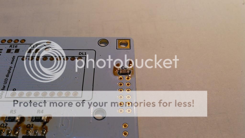
Don't forget C4 100nF. This must be soldered as well.
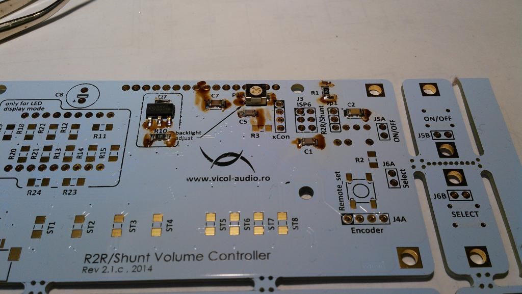
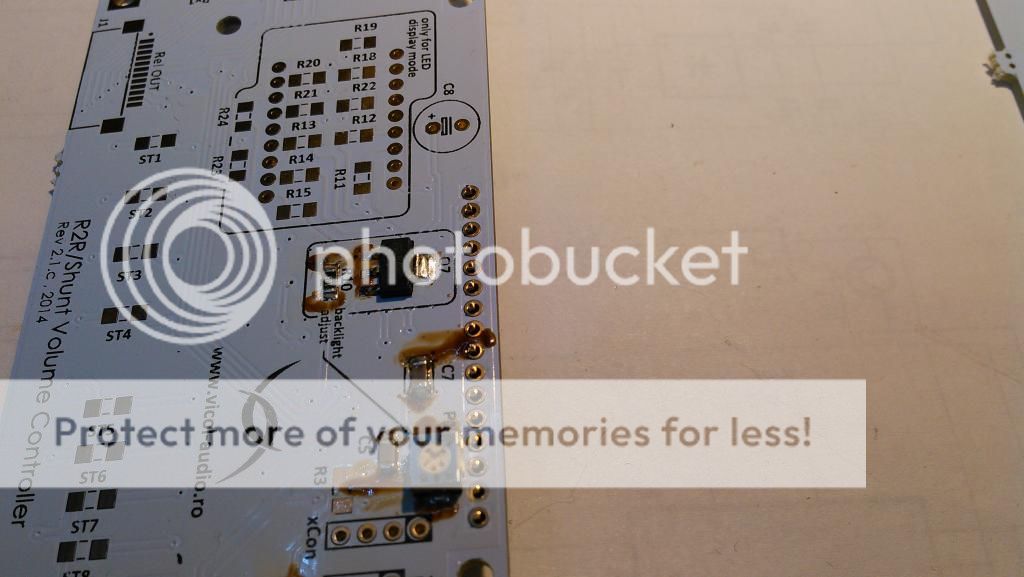
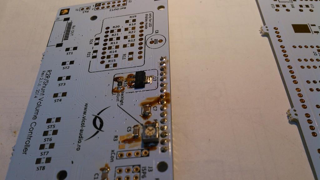
Turn the board on the other side and solder C1, C2, C5, C7, R10, Q7, P1
You may now separate Display board from Relays board and solder LCD conector.
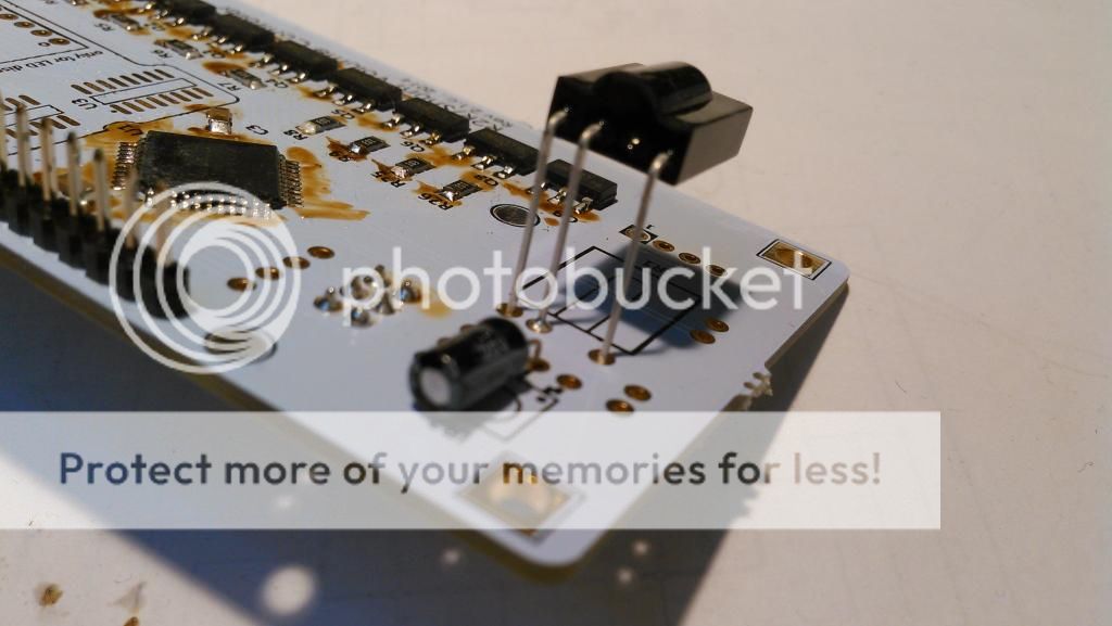
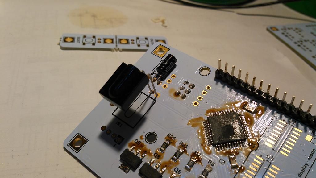
Even this is optional, I found that infrared receiver may benefit from a 10uF decoupling cap.Add one across C2 exacly as you can see in below picture.
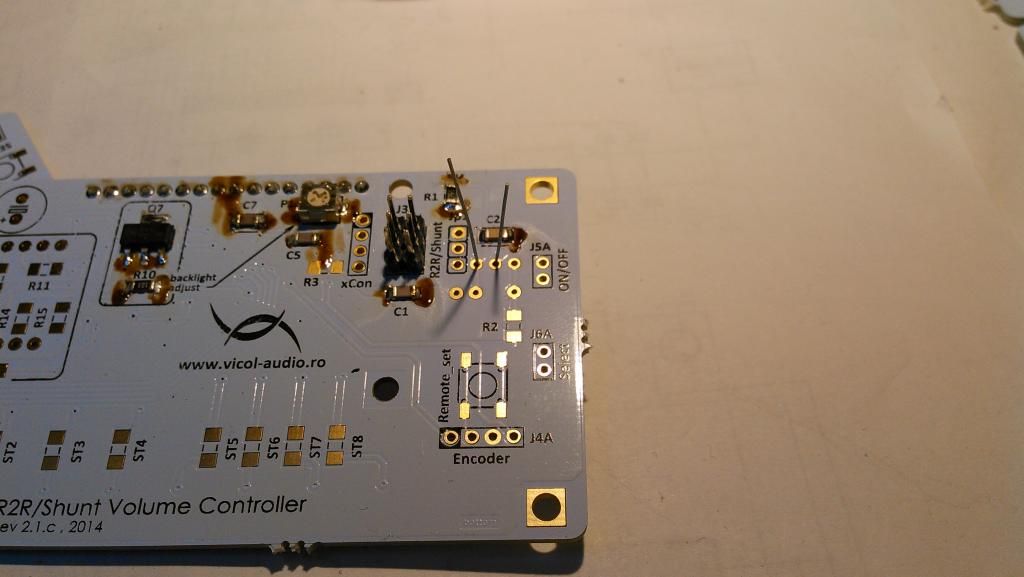
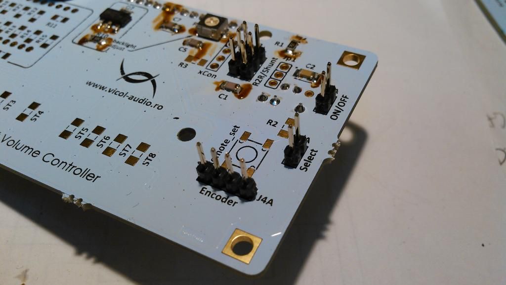
Solder ISP6 connector for firmware programming.
Solder other conectors for encoder and push buttons - select and power on/off.
Now solder C8. This will allow a smooth turn off of LCD. A value between 330uF and 1000uF is recommended.
Before starting to solder on Relays board, last component to be soldered on this board is infrared receiver.
LCD will be mounted after we solder ribbon cable and perform board cleaning.
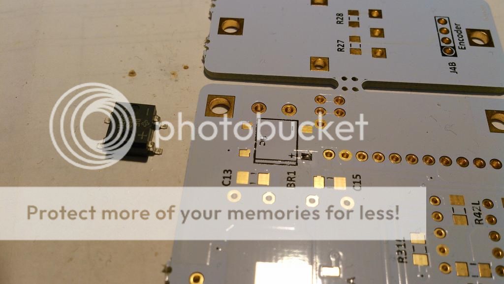
Realys board
Start mounting bridge BR1. Use same technique, a small drop of solder to fix the component in right position and only after that perform full soldering.
Prepare the board for smd soldering.
ATTENTION!
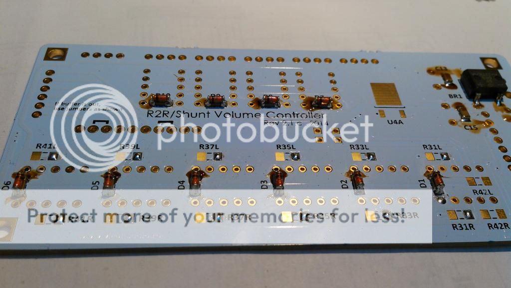
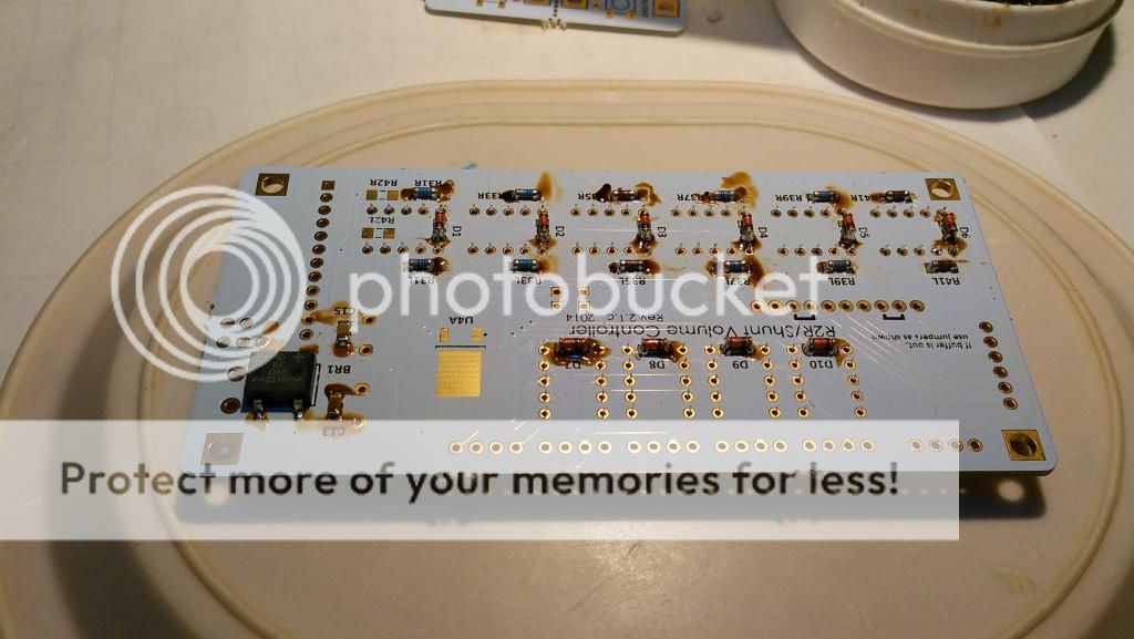
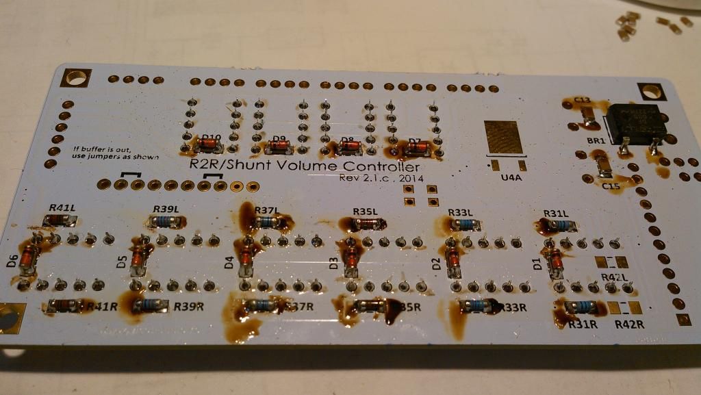
Solder first decoupling 100nF capacitors. On top of these will be mounted D1 - D10 diodes.
Finish to solder these capacitors, but add a little more solder as you can see in below picture.
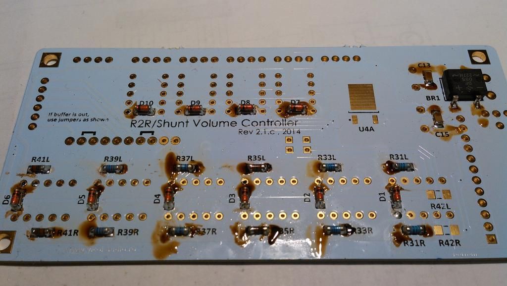
Now you can solder diodes on top of these decoupling caps.
At this point we can continue with R-2R resistor network.
There are three set of standard melf resistors that may be practically used here E96 (1% tolerance) and E192 (0.5%;0.1% and higher tolerances).
Please use only melf resistors or Z-foil types with at least 1% tolerance. Using standard SMD resistors will lead you to an ordinary volume controller. You have been warned !
Values for R-2R resistor network are:
R30=12K
R31=100K
R32=2,7K
R33=47K
R34=5,6K
R35=27K
R36=15K
R37=18K
R38=56K
R39=12K
R40=390K
R41=10K
Another set of values are:
R30=11K
R31=91K
R32=2,7K
R33=47K
R34=5,6K
R35=27K
R36=15K
R37=16K
R38=51K
R39=12K
R40=390K
R41=10K
Solder all resistors on one pcb side and after that on the other side.
Don't forget to "prepare" board for soldering. Notice that solder bulb for 7805 regulator.
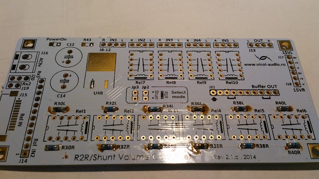
Optional, if you like glowing boards, add a smd LED and his associated resistor.
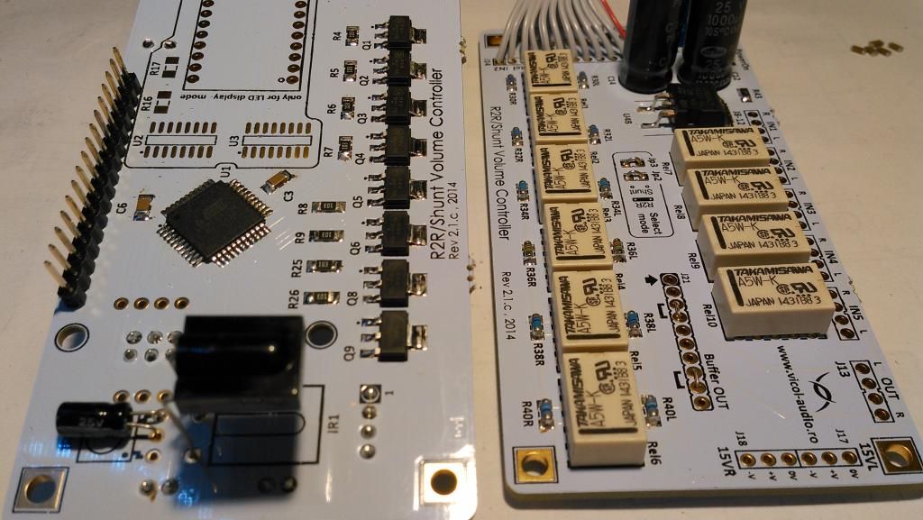
We have reached the point where we can solder Takamisawa relays. A wide range or relays can be used.
However when you choose another type pay attention on folowing parameters:
- operating nominal voltage - must be 5V
- coil resistance - a too low value will overheat your microcontroller or fail to operate.
- connect and release time - a too big one will generate annoying clicks in your speakers
- contact resistance - as low as possible
Now pay attention on how these relays are mounted. Once soldered it will be hard to remove them.
To solder all relays at once I use a small flat plastic plate to turn the board.
... and soldering.
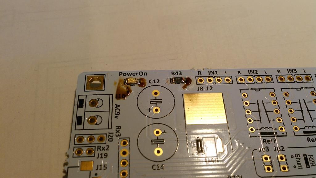
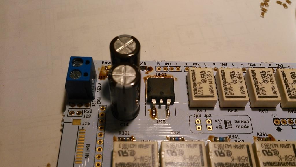
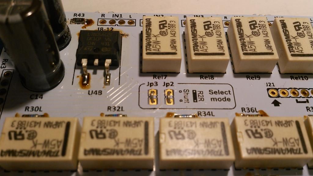
Solder 7805 regulator. C12 and C14 can be any value between 680uF to 2200yF at 16V min. No special requirements, no need to look for fancy capacitors.
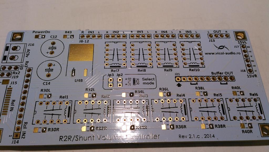
R-2R resistor network is completely isolated from power supply.
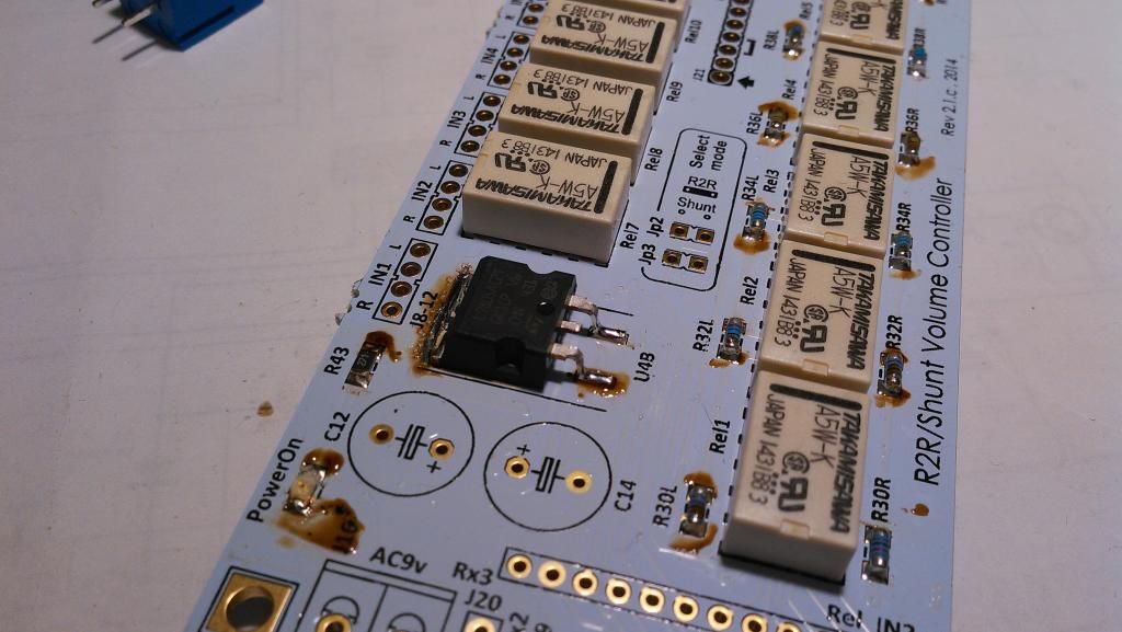
The board was designed to be very adaptive and support R-2R and shunt operation. However, for each operation mode a different firmware must be loaded.
As we are going for R-2R, Jp2 and Jp3 must be in place.
At output, a buffer was designed for OEM's. This must be strapped as per below picture - J21 connector.
Push-buttons board & Encoder board
Prepare the other two small boards. One is for on/off and select push buttons (left) and one for rotary encoder (right).
Start assembley
Connect 12 wire ribbon cable between Display board and Relays board.
You may use connectors specified in BOM, or just simply solder - which I consider to be the best, but not so eye candy.
About lenght - so far we have tested perfect functionality with a 5 meter ribbon cable length. Usually you should don't need more than 40cm.
Prepare wires.
Solder ribbon cable on Relays board. Red wire is at Vcc+.
Now solder on Displays board. See red wire, pay attention on how this cable is soldered.
Finally time to clean the boards with isopropylic alcohol.
Picture after cleaning. 🙂
Go to part 2
Due wiki limitation to 50 images, it was split into parts.
Part 2
[h=Bill of Materials]%1[/h]
BoM is available for download from below link.
https://docs.google.com/spreadsheet...HiIyZQHBxJVBQxT6wF42agyGZU/edit#gid=173448974
Please note that depending on firmware type some parts may not be used.
[h=Schematic and documentation]%1[/h]
Main website page http://vicol-audio.ro/volume-controller.php
Schematic -> http://www.diyaudio.com/forums/grou...volume-controller-4-inputs-5.html#post4109749
Connections -> http://vicol-audio.ro/img/volume-controller/wiring.png
Please note that trafo must be 6Vac @ min 1A.
[h=Assembly instructions]%1[/h]
To mount this KIT you need to use a very good soldering station. I suggest one of these:
Velleman VTSSC50NU or Hakko Digital FX888D
Make sure that you are using a anti-static ESD protected workbench. Any electrostatic discharge may destruct atmel or alter firmware.
Solder I use is http://www.tme.eu/en/details/sn96a-0.5_0.5/solders-wires/sn96a-0505#
If you prefer lead http://www.tme.eu/en/details/lc60-0.50_0.5/solders-wires/lc60-05005#
I'm using a lot of colophony (rosin), depending on your soldering stile you may need more or less.
Display board
Start mounting by soldering Atmel microcontroller. First solder only one pin and when you have perfectly placed the IC over pads solder the rest.
Don't hurry to clean the board, This will be done at the end using isopropyl alcohol.
Now solder decoupling caps for microcontroller and prepare the board for transistor and resistor soldering - a very small drop of solder only on one side.
Align and solder all 10K resistors and BCP56-16 transistors.
Finish the soldering after all parts are perfectly aligned.
Don't forget C4 100nF. This must be soldered as well.
Turn the board on the other side and solder C1, C2, C5, C7, R10, Q7, P1
You may now separate Display board from Relays board and solder LCD conector.
Even this is optional, I found that infrared receiver may benefit from a 10uF decoupling cap.Add one across C2 exacly as you can see in below picture.
Solder ISP6 connector for firmware programming.
Solder other conectors for encoder and push buttons - select and power on/off.
Now solder C8. This will allow a smooth turn off of LCD. A value between 330uF and 1000uF is recommended.
Before starting to solder on Relays board, last component to be soldered on this board is infrared receiver.
LCD will be mounted after we solder ribbon cable and perform board cleaning.
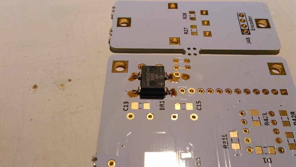
Realys board
Start mounting bridge BR1. Use same technique, a small drop of solder to fix the component in right position and only after that perform full soldering.
Prepare the board for smd soldering.
ATTENTION!
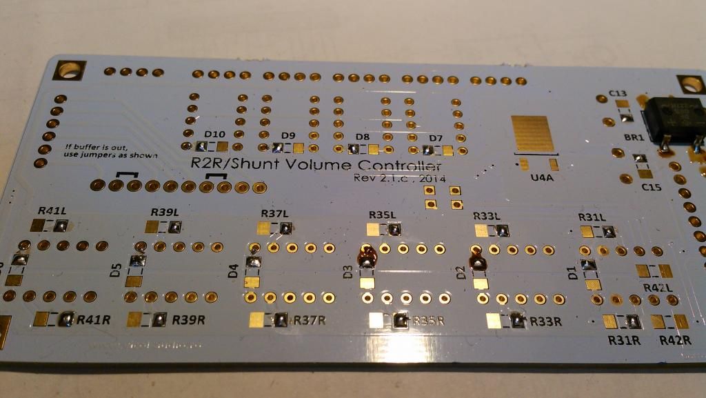
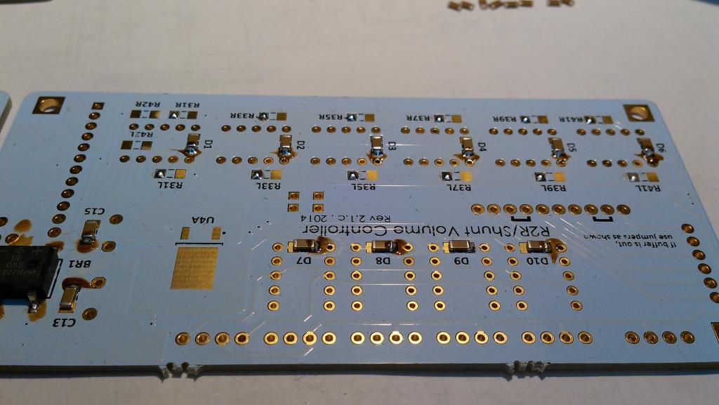
Solder first decoupling 100nF capacitors. On top of these will be mounted D1 - D10 diodes.
Finish to solder these capacitors, but add a little more solder as you can see in below picture.
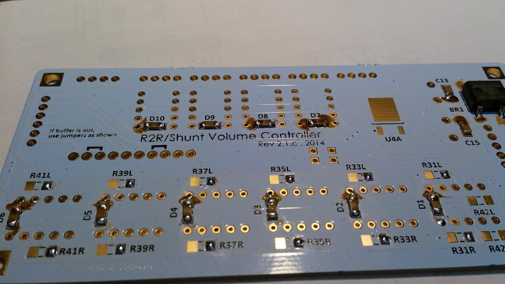
Now you can solder diodes on top of these decoupling caps.
At this point we can continue with R-2R resistor network.
There are three set of standard melf resistors that may be practically used here E96 (1% tolerance) and E192 (0.5%;0.1% and higher tolerances).
Please use only melf resistors or Z-foil types with at least 1% tolerance. Using standard SMD resistors will lead you to an ordinary volume controller. You have been warned !
Values for R-2R resistor network are:
R30=12K
R31=100K
R32=2,7K
R33=47K
R34=5,6K
R35=27K
R36=15K
R37=18K
R38=56K
R39=12K
R40=390K
R41=10K
Another set of values are:
R30=11K
R31=91K
R32=2,7K
R33=47K
R34=5,6K
R35=27K
R36=15K
R37=16K
R38=51K
R39=12K
R40=390K
R41=10K
Solder all resistors on one pcb side and after that on the other side.
Don't forget to "prepare" board for soldering. Notice that solder bulb for 7805 regulator.
Optional, if you like glowing boards, add a smd LED and his associated resistor.
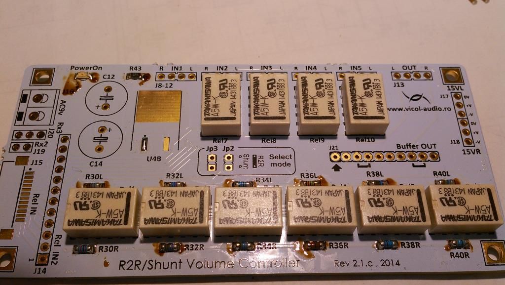
We have reached the point where we can solder Takamisawa relays. A wide range or relays can be used.
However when you choose another type pay attention on folowing parameters:
- operating nominal voltage - must be 5V
- coil resistance - a too low value will overheat your microcontroller or fail to operate.
- connect and release time - a too big one will generate annoying clicks in your speakers
- contact resistance - as low as possible
Now pay attention on how these relays are mounted. Once soldered it will be hard to remove them.
To solder all relays at once I use a small flat plastic plate to turn the board.
... and soldering.
Solder 7805 regulator. C12 and C14 can be any value between 680uF to 2200yF at 16V min. No special requirements, no need to look for fancy capacitors.
R-2R resistor network is completely isolated from power supply.
The board was designed to be very adaptive and support R-2R and shunt operation. However, for each operation mode a different firmware must be loaded.
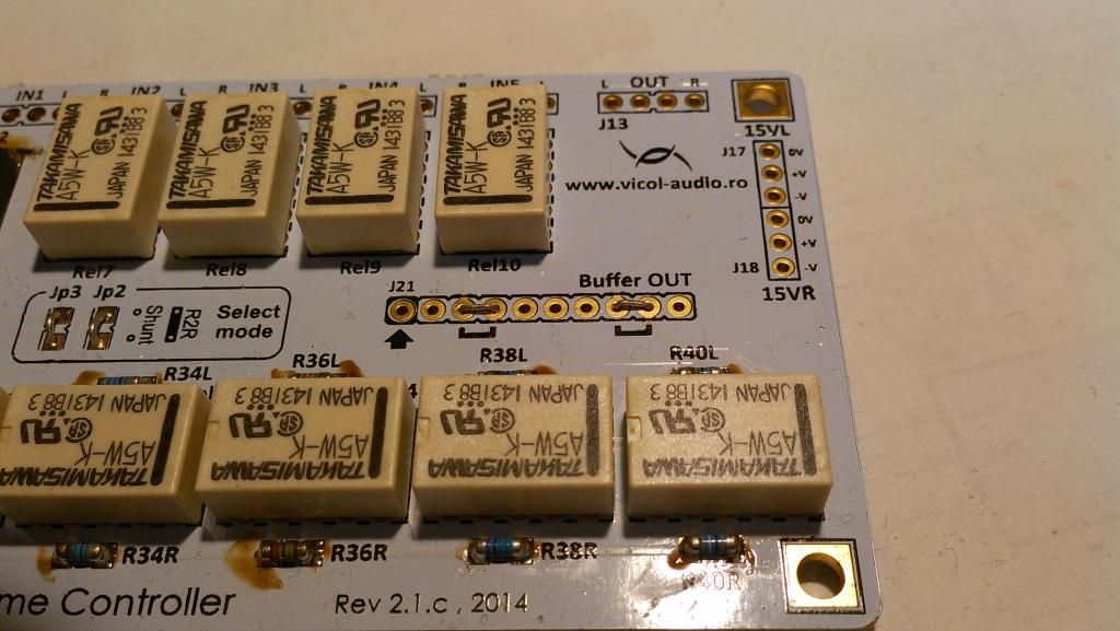
As we are going for R-2R, Jp2 and Jp3 must be in place.
At output, a buffer was designed for OEM's. This must be strapped as per below picture - J21 connector.
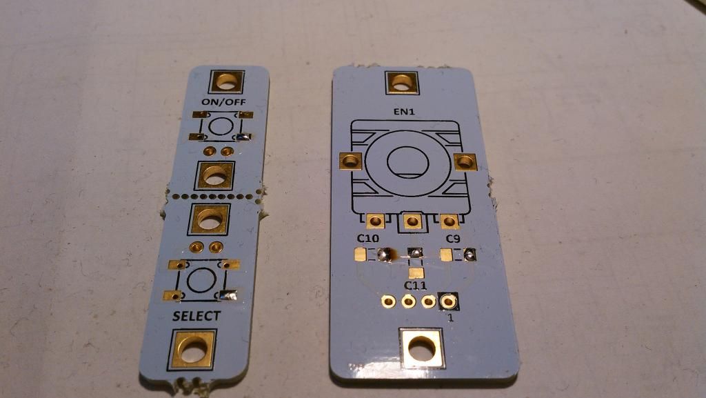
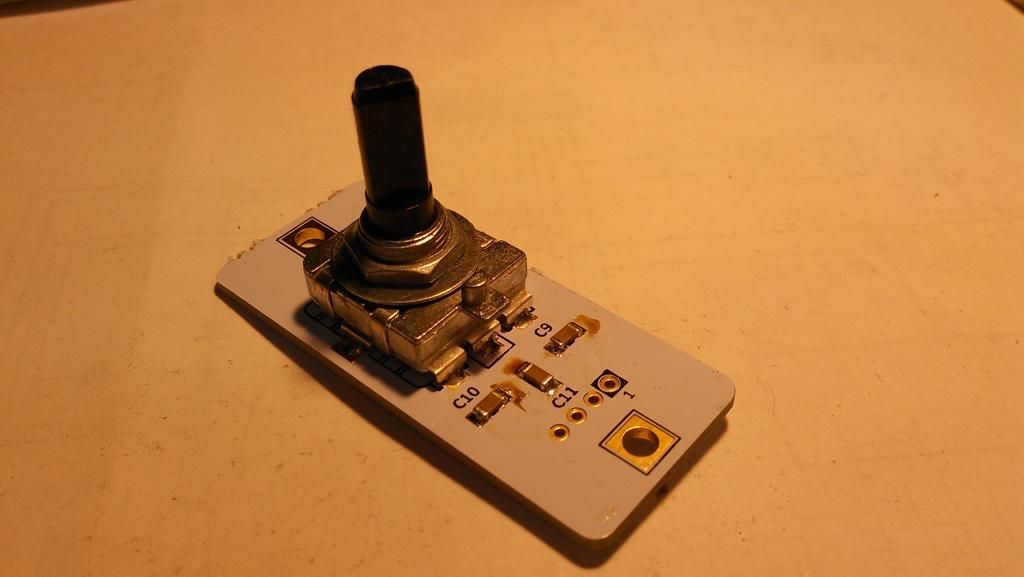
Push-buttons board & Encoder board
Prepare the other two small boards. One is for on/off and select push buttons (left) and one for rotary encoder (right).
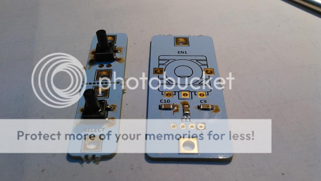
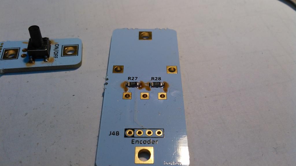
Start assembley
Connect 12 wire ribbon cable between Display board and Relays board.
You may use connectors specified in BOM, or just simply solder - which I consider to be the best, but not so eye candy.
About lenght - so far we have tested perfect functionality with a 5 meter ribbon cable length. Usually you should don't need more than 40cm.
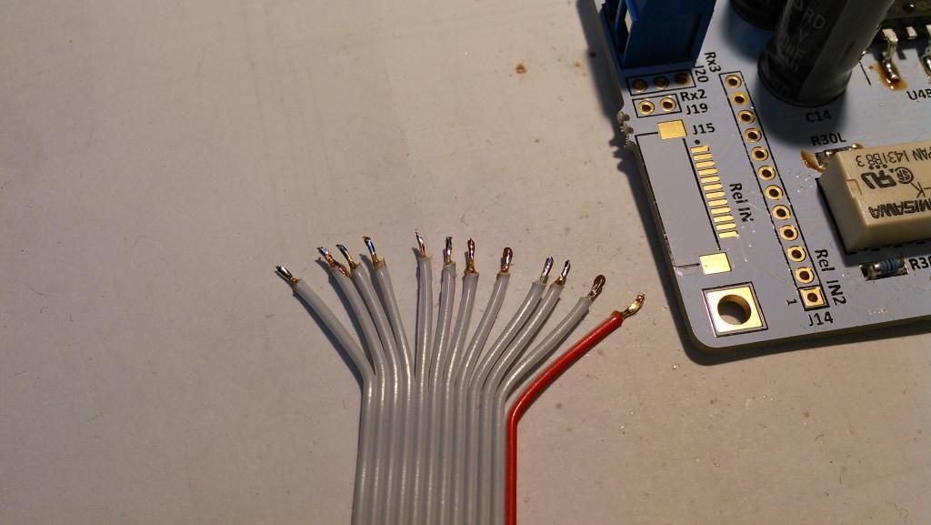
Prepare wires.
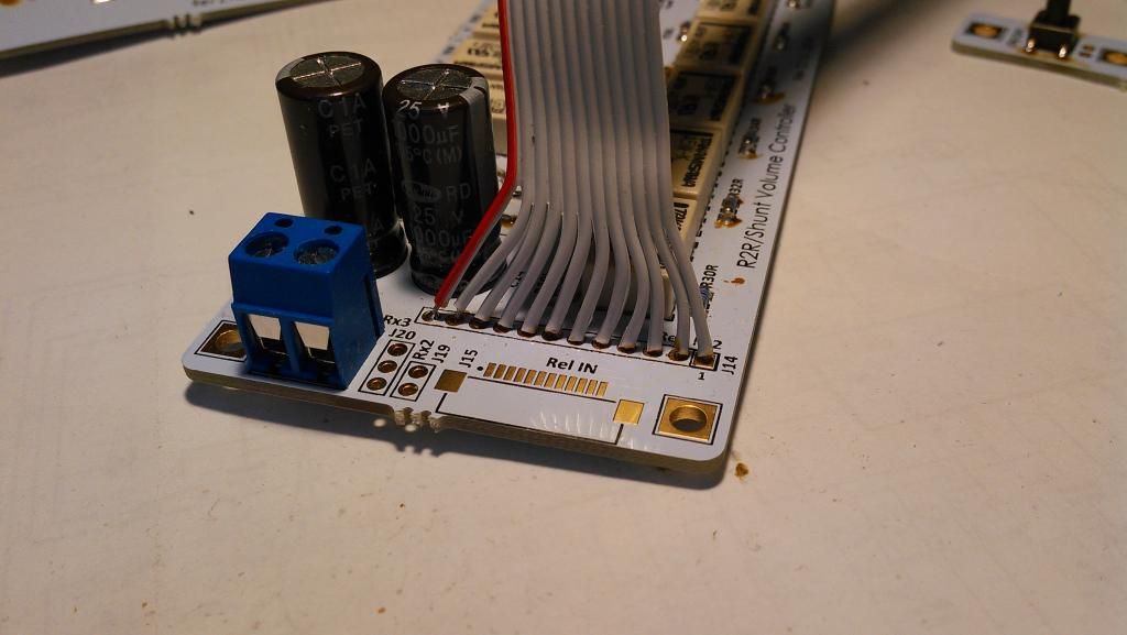
Solder ribbon cable on Relays board. Red wire is at Vcc+.
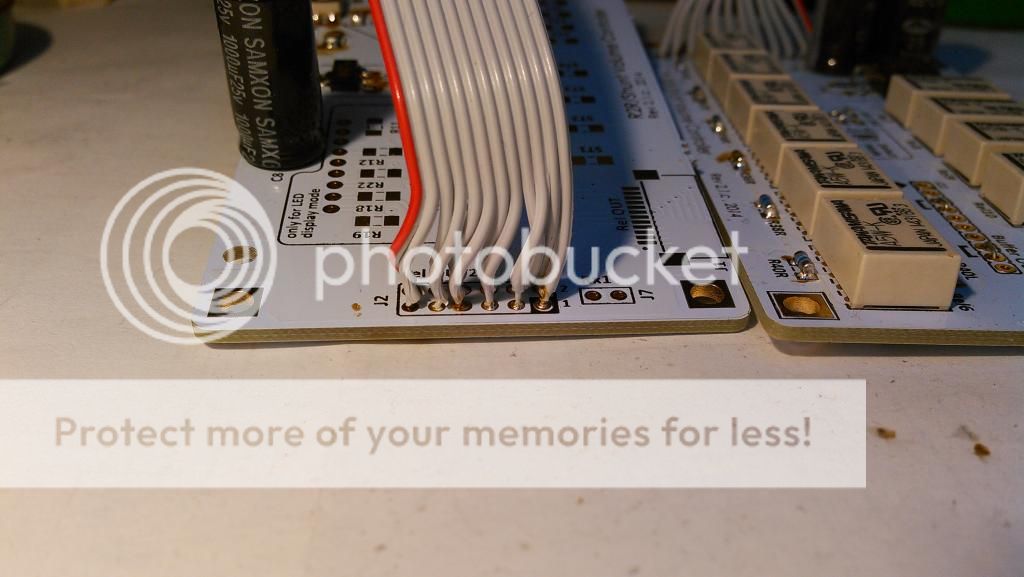
Now solder on Displays board. See red wire, pay attention on how this cable is soldered.
Finally time to clean the boards with isopropylic alcohol.
Picture after cleaning. 🙂
Go to part 2
Last edited by a moderator: