Just about to start my TSE - and plan to mount all components on the underside of the board (apart from tube mounts) to allow me to mount the board immediately beneath a sheet of aluminium drilled for the tubes. Originally I was going to put just the resistors on top - but I figure better having no heat-producing components at all between the board and the aluminium cover.
Anybody built it this way?
Will doing this cause me any problems apart from that extra bit of concentration as I translate component positions?
Anybody built it this way?
Will doing this cause me any problems apart from that extra bit of concentration as I translate component positions?
Just about to start my TSE - and plan to mount all components on the underside of the board (apart from tube mounts) to allow me to mount the board immediately beneath a sheet of aluminium drilled for the tubes. Originally I was going to put just the resistors on top - but I figure better having no heat-producing components at all between the board and the aluminium cover.
Anybody built it this way?
Will doing this cause me any problems apart from that extra bit of concentration as I translate component positions?
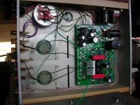
I built my 300B TSE this way, and I'm presently building a 45 version this way also. Just triple check the pinouts, and make sure the cap polarities are correct. The filament voltage regulator is the only part that requires significant manipulation of the legs. My PCB is "hanging" off of the underside of the top panel with standoffs cut to the proper length to allow the tube sockets to be flush with the top deck.
I also marked the underside with a sharpie for important test points, transformer connections, etc....
Thanks, Boywonder.
Photograph?
As Evan mentioned above, don't be shy on the size of the heatsink for the filament regulator.....
Attachments
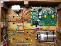
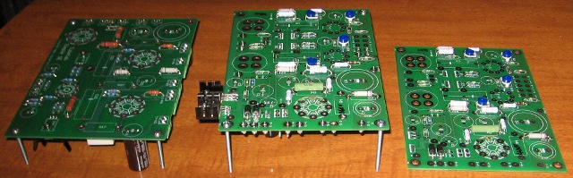
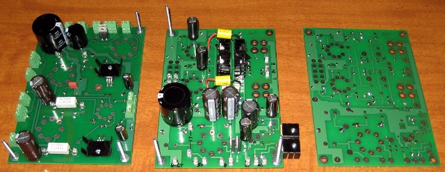
a couple more things........note that Evan has the heatsink for the filament regulator top mounted and poking through the deck with a heatsink (one way to go) and on mine it's under the board with a large heatsink and a couple of slots to aid airflow. It gets hot, and I think that the heat is proportional to current, so 2.5V tubes will have the regulator dissipating more heat than 300B's due to more current draw at lower voltages.
I bottom mounted everything except the tube sockets because I was slightly uncomfortable with having HV resistors, etc very close to the underside of the aluminum top deck.
I bottom mounted everything except the tube sockets because I was slightly uncomfortable with having HV resistors, etc very close to the underside of the aluminum top deck.
so 2.5V tubes will have the regulator dissipating more heat than 300B's due to more current draw at lower voltages.
There are board jumpers for feeding the regulator 3.3 volts or 6.5 volts (depending on the power transformer). As for regulator heat the 45 tubes produce the least heat. A piece of angle aluminum bolted to the (metal) chassis is usually sufficient. The 300B is next. This will require some supplemental heat sink. The size will be dependent on air flow. My Lexan amp with no airlow required a lerge heat sink liberated from a Pentium 1 chip. The 2A3 will generate the most heat. A large heat sink will be required. Some tubes called 2A3 may draw over 2.5 Amps each. This can force the regulator into dropout causing hum.
I initially build my SSE and one TSE inverted:
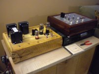
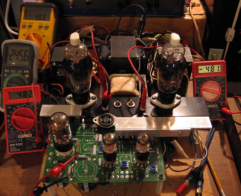
Here it is being tested with 45s:
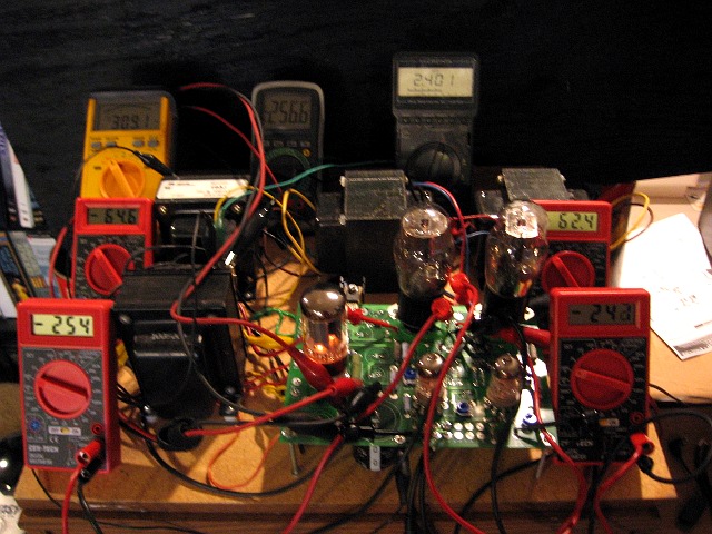
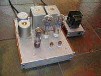
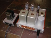
Later I started designing the chassis and realized that I had just enough clearance to fit the parts topside. Here you can see it on the breadboard again, trying out the new arrangement with VT-225s. That small 1" angle aluminum (in wide open air) is just enough to keep the regulator working with 300Bs installed. It gets very hot, but doesn't shut down. In the real chassis, the two bars you see will be thermally bonded to a very large top-side heatsink.
Here it is being tested with 45s:
Later I started designing the chassis and realized that I had just enough clearance to fit the parts topside. Here you can see it on the breadboard again, trying out the new arrangement with VT-225s. That small 1" angle aluminum (in wide open air) is just enough to keep the regulator working with 300Bs installed. It gets very hot, but doesn't shut down. In the real chassis, the two bars you see will be thermally bonded to a very large top-side heatsink.
- Status
- Not open for further replies.
- Home
- More Vendors...
- Tubelab
- Building the TSE board upside down