That looks OK conceptually but I would still question the 100 ohm value tbh. The opto has to work hard to generate the needed 700mv or so to turn the second transistor... and it doesn't seem to have anywhere to get that current from, just the 220k.
Would the opto alone not suffice?
Would the opto alone not suffice?
I've included the additional transistor because during a DC fault, the capacitor must discharge through the 100R resistor and the transistor. The capacitor will be charged to just over 15V so, through the 100R, that's 150mA initial discharge current. The opto is only specified for 50mA continuous and 100mA for <1us. Hence, I decided the opto wasn't rated sufficiently on its own. I could be missing something though, of course.
Thanks,
James
Thanks,
James
Hello James,
I apologise for not responding to your TVS question yet...
As I want to use through-hole components, my choice fell on the axial leaded "5kp" series made by "Littlefuse". It is strongly recommended to choose the breakdown voltage several volts lower than Vdsmax of the chosen NMOSFET type, in order to protect it.
Hope this helps,
Winfried
Hi,
I am starting a new guitar amp project (solid state) and will be starting a thread on it at some point soon. I want to start by building a speaker protection PCB so that I don't destroy the speaker when testing it.
Thanks,
James
A DC protect wont stop you from over driving a speaker.
It will protect from blown outputs though.
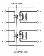
Interesting opto coupler device that works off RF.
I did a similar circuit but using a 8 pin PIC micro to detect DC.
Hi,
I realise it won't keep the speaker totally safe but it will at least guard it against catastrophic DC fault conditions, hopefully. I'm going to incorporate some other protection circuitry in the power amp too to try and further reduce the risk of speaker damage.
What do you mean by the optocoupler working off RF?
Thanks,
James
There is clearly no supply to secondary side of opto coupler so what they do is transmit RF across the gap and turn that into a supply voltage for secondary side.
Ah okay, I understand now, I thought you were talking about the optocoupler in the DC detector. I didn't realise it worked like that, I assumed it was some kind of capacitive coupling.
Hi,
I thought I should post back here now I've completed the circuit. I ended up changing the circuit around the opto-coupler slightly, as shown in the schematic. The switch-off was too slow when connected as a Darlington.
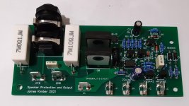
The boards arrived yesterday and I've just soldered up and tested them. I combined the speaker protection circuit with the output jack, Zobel network and current-sense resistor. This is being used in a guitar amp build and I wanted to save a bit of money on 2oz copper boards by combining the two.
All seems to be working fine. The startup delay, DC detection and loss-of-AC detection all work as they should and the current through the MOSFET driver is as it should be. When off, the resistance between the input and output terminals is too high for my multimeter to measure. When on, it reads zero. I haven't tested it with an amp yet but have done with a signal generator. With no load attached, the signal is present on the output jack even when switched off. With a load of a few k, it virtually disappears when off. This leads me to believe that the MOSFET relay does not act as a proper open-circuit when off. Any ideas?
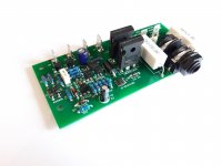
I've attached a couple of pictures of the finished board. Thank you again for all the help!
Thanks,
James
I thought I should post back here now I've completed the circuit. I ended up changing the circuit around the opto-coupler slightly, as shown in the schematic. The switch-off was too slow when connected as a Darlington.
The boards arrived yesterday and I've just soldered up and tested them. I combined the speaker protection circuit with the output jack, Zobel network and current-sense resistor. This is being used in a guitar amp build and I wanted to save a bit of money on 2oz copper boards by combining the two.
All seems to be working fine. The startup delay, DC detection and loss-of-AC detection all work as they should and the current through the MOSFET driver is as it should be. When off, the resistance between the input and output terminals is too high for my multimeter to measure. When on, it reads zero. I haven't tested it with an amp yet but have done with a signal generator. With no load attached, the signal is present on the output jack even when switched off. With a load of a few k, it virtually disappears when off. This leads me to believe that the MOSFET relay does not act as a proper open-circuit when off. Any ideas?
I've attached a couple of pictures of the finished board. Thank you again for all the help!
Thanks,
James
Attachments

A solid state circuit breaker will not present as high an impedance as does a mechanical relay. In your particular circuit the TVS could make the off-state impedance even lower. I might want to test it again with the TVS removed.
I also came to wonder, when seeing the data sheet of the TVS showing an avalanche voltage of up to 16V, what the power rail voltage of the amp is. I mean if the TVS was properly chosen to work with the power amp supply voltage, up to +/-16V if that is the case, there might not be the need for a TVS to begin with as the MOSFETs have been well protected by the generous 150V Vds rating.
With that being said your solid state relay as-is seems to be performing well enough with its off-state impedance for its purpose.
Thanks for pointing out about the TVS, I've specified the wrong one! The power amp supply voltage +-35V so I'm going to need to order a different TVS. I don't know how I ended up mixing them up, I thought I'd picked one with a ~100V avalanche voltage.
Thanks,
James
Thanks,
James
Those boards look super neat 
As to the 'off-ness', well at DC it is truly OFF, what you are observing is the junction capacitance of the two FET's coupling the signal across them. It's not much but certainly enough to show a signal present unless you have a load attached. You won't hear anything break through with a speaker, sensitive headphones and you would hear some HF get through.
As to the 'off-ness', well at DC it is truly OFF, what you are observing is the junction capacitance of the two FET's coupling the signal across them. It's not much but certainly enough to show a signal present unless you have a load attached. You won't hear anything break through with a speaker, sensitive headphones and you would hear some HF get through.
I've tested it with an amplifier now. It does indeed shut the speaker off completely so all is good! I just need to replace that TVS with a correct part.
How hot does R6 get? 20mA @ ~30V = 0.6W ... if that is correct then the resistor needs to be fairly large.
Hi,
I've changed a couple of component values because those resistors did indeed get too hot. I'd originally calculated them for 20V supply. The new values are
R6=5k6
R11=4k7
I've also changed the TVS to P6KE68CA
I've attached the PCB files here in case they're useful to anyone. It's a pretty niche design though. It's for a guitar amp and has the output Jack, Zobel network and current-sense resistor on the board, These could all be omitted though.
Thanks,
James
Attachments

Can one Si8752 drive two pairs of Mosfets in a stereo setup?
... I am looking at using Mosfets instead of a mechanical relay with the old SC front end for DC and AC detection. That should reduce DC detection to 0.6-0.65V and be much faster than an optocoupler. I want to run it from the main PSU rails so I am adding an extra trannie to detect loss of the negative rail. Also adding a linear transistor regulator with h/sink to set the downstream voltage to ~30V, irrespective of the PSU rails up to +/- 60Vdc.
... I am looking at using Mosfets instead of a mechanical relay with the old SC front end for DC and AC detection. That should reduce DC detection to 0.6-0.65V and be much faster than an optocoupler. I want to run it from the main PSU rails so I am adding an extra trannie to detect loss of the negative rail. Also adding a linear transistor regulator with h/sink to set the downstream voltage to ~30V, irrespective of the PSU rails up to +/- 60Vdc.
- Home
- Amplifiers
- Solid State
- Building speaker protection board with MOSFET relays