Hey folks,
So far I only built pre-made speaker sets, but now I'd like to try my own subwoofer, which should fit in the living room corner without affecting the interior design very much. Therefore I'm pretty limited with the volumes and measurements. We do not listen that loud, since we live in a row house and want to keep peace with our neighbors 😉 But what I want is a real deep playing system, a friend of mine has a Sub with f3 20Hz, and for explosions and so on this is pretty impressive. My fronts and center have a crossover frequency of 40Hz, so I really just care about the Freqs around 40 and lower...
Okay, so I have around 55 liters of real inside volume (already substracted speaker). I plan to have a downfiring sub, since we have a massive tile floor and my wifey does not want to see the speaker itself. And I also hope that maybe my room modes are getting better (which are corrected by a DSPeaker Anti-Mode)
I played around a bit (or better said weeks) with WinISD, tried closed, vented, bandpass, and so on, and the only ideas which make sense (for me) is an enclosure with passive radiator (since many bass reflex tubes would end up being too long).
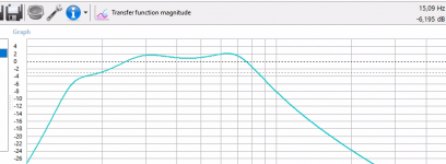
My favorite is now a DD Audio 2510d D4 speaker, which is a car audio speaker, but fits in my eyes good into my setup (box volume and usage of radiator). I attached the charts for transfer function magnitude, SPL and cone excursion, which have been the interesting charts for me (Correct me, maybe I have to check much, much more? I'm pretty newbish here.)
If i set the wattage for output signal >200W the Xmax is reached at 18Hz, but according to the data sheet of speaker the Xmech is somewhere at 55mm, so even if i power it with 500 Watt theres still plenty of space until speaker takes damage?
Ok, I'm going to attach the charts and WinISD file. Maybe you can give me some input, if this makes sense in general, or if I'm totally wrong with my limited knowledge...
View attachment 930946
View attachment 930947
View attachment 930948
View attachment 930949
So far I only built pre-made speaker sets, but now I'd like to try my own subwoofer, which should fit in the living room corner without affecting the interior design very much. Therefore I'm pretty limited with the volumes and measurements. We do not listen that loud, since we live in a row house and want to keep peace with our neighbors 😉 But what I want is a real deep playing system, a friend of mine has a Sub with f3 20Hz, and for explosions and so on this is pretty impressive. My fronts and center have a crossover frequency of 40Hz, so I really just care about the Freqs around 40 and lower...
Okay, so I have around 55 liters of real inside volume (already substracted speaker). I plan to have a downfiring sub, since we have a massive tile floor and my wifey does not want to see the speaker itself. And I also hope that maybe my room modes are getting better (which are corrected by a DSPeaker Anti-Mode)
I played around a bit (or better said weeks) with WinISD, tried closed, vented, bandpass, and so on, and the only ideas which make sense (for me) is an enclosure with passive radiator (since many bass reflex tubes would end up being too long).
My favorite is now a DD Audio 2510d D4 speaker, which is a car audio speaker, but fits in my eyes good into my setup (box volume and usage of radiator). I attached the charts for transfer function magnitude, SPL and cone excursion, which have been the interesting charts for me (Correct me, maybe I have to check much, much more? I'm pretty newbish here.)
If i set the wattage for output signal >200W the Xmax is reached at 18Hz, but according to the data sheet of speaker the Xmech is somewhere at 55mm, so even if i power it with 500 Watt theres still plenty of space until speaker takes damage?
Ok, I'm going to attach the charts and WinISD file. Maybe you can give me some input, if this makes sense in general, or if I'm totally wrong with my limited knowledge...
View attachment 930946
View attachment 930947
View attachment 930948
View attachment 930949


lvis,1) I plan to have a downfiring sub, since we have a massive tile floor and my wifey does not want to see the speaker itself.
2)If i set the wattage for output signal >200W the Xmax is reached at 18Hz, but according to the data sheet of speaker the Xmech is somewhere at 55mm, so even if i power it with 500 Watt theres still plenty of space until speaker takes damage?
1) Long excursion downfiring subwoofers tend to sag over time, which reduces usable excursion and increases distortion. Using grill cloth to match decor or firing the woofers from the back side can increase WAF (wife approval factor) without the inevitable sagging problem with downfiring.
2)Most sub users will use DSP (digital signal processing) to shape the sub's response, and HP (low cut) filters below the Fb (box tuning frequency) as a ported or passive radiator has little output below Fb. With an Fb of 23Hz (like yours) a BW24 filter at 20 Hz would eliminate the useless excursion (and wasted power used) below FB, and allow another 4+ dB input/output before reaching Xmax.
That said, most modern long excursion woofers will not have have as much excursion past Xmax as predicted, as the suspension progressively becomes stiffer, while magnetic force becomes less past Xmax.
However, passive radiators do hit a hard limit, you also need to figure their excursion, which will be at maximum at Fb. Often, 2 passive radiators are needed to provide enough excursion for one long-throw woofer.
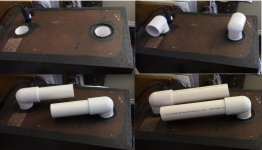
Which brings up another possibility- using exterior rear ports with right angle bend can also hide them without much intrusion on real estate.
The example below using schedule 40 PVC plumbing parts with pipe couplings for the “built in” ports, adding 90 degree slip elbows, then exterior pipes from the elbows also allows quick Fb changes- an octave difference between the four options shown.
Art
Attachments
Last edited:
Strange, I cannot quote your post, Art.
Well, regarding the downfire thanks for these points of view. I might place it as front fire (radiator will then stay downfire), hope my wife will not kill me, hehe. Backside makes no sense, as the Sub is fitted into corner and there's only around half an inch to the wall...
I had a similar idea regarding plumbing pipes, but only for inside use. Cannot place it outside, as mentors I have no space left to the walls :/
WinISD unfortunately does not show the radiator excursion, bit since the radiator is 12" and not like the speaker 10, as well as the fact that XMax of radiator is 10mm more than than the XMax of speaker, my amateurish opinion is that the radiator will not hit it's limits?
Passive radiators are heavy, their mass makes them even more subject to sag than a driver, since there is no power to help them re-center during use. But if you can't spare an inch or two between the wall, you can look forward to the "sands of time" shifting ...
The displacement of the passive radiator should be twice (or more..) of the active driver, displacement is Sd x excursion (Xmax). Sounds like yours is around that.
Xmax of a passive is basically Xlim, it can't move more when it hits the limit, which may sound like a flapping noise, so definitely better to go more than what you might need.
Also, the tuning will change a bit as the suspension limits are approached.
Yep a bit more than twice...The displacement of the passive radiator should be twice (or more..) of the active driver, displacement is Sd x excursion (Xmax). Sounds like yours is around that.
Never considered the sag thing. As you say "over time", what do you mean by it? I don't expect to have the subwoofer 20 years working, but 10 years or so would be fine 🙂
Anyways, also talked to wife, we could do both membranes front firing, I just have to care about covering them
GM, which formula did you apply? I used one I found in AVS forums, here the radiator is at 12% while the speaker is lower than 5%...
Beside the sag aspect, does my comination of speaker and radiator make sense anyways? Or I'm just building crap when I do this? Are there any more parameters in WinISD (or similar) I have to take care of? Any other simulations to do?
WinISD unfortunately does not show the radiator excursion
Strange, it looks like you're using the same version as me, does your program not have this option?
Attachments
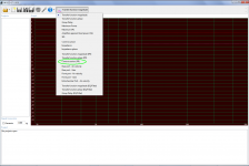
Damn, I'm so blind. Of course I have this option as you showed...
OK then the radiator idea currently does not work out due to hitting Xmax early. Maybe i try 2 smaller ones...
OK then the radiator idea currently does not work out due to hitting Xmax early. Maybe i try 2 smaller ones...
Would a 6th order Bandpass make sense for me, is it even possible to design and build for a newbie like me?
I thought about using plumbing pipes inside with angles to get them outside. Sorry for my bad painting "sketch". Blue are the pipes
Effective diaphragm diameter is 216mm, the 2 vent pipes would have 60mm each. Or would i need more diameter here?


I thought about using plumbing pipes inside with angles to get them outside. Sorry for my bad painting "sketch". Blue are the pipes
Effective diaphragm diameter is 216mm, the 2 vent pipes would have 60mm each. Or would i need more diameter here?
Attachments
GM, which formula did you apply?
Beside the sag aspect, does my comination of speaker and radiator make sense anyways?
The one I posted for the driver. 😉: Resources - Woofer Mount Up Down
Didn't bother with the PR since by definition it would exceed the 5 % max rule by a wide margin.
Personally have always used dual opposing PRs to ~cancel out box vibration at high excursion.
Would a 6th order Bandpass make sense for me, is it even possible to design and build for a newbie like me?
As a general rule it's not a good plan to vent weak motored [high Qts'] drivers unless as some form of TL, so morphing it into a tapped pipe or horn [TTQWT, TH] is what I'd do, but gather that you don't have enough room space for one unless it can be [very] tall, othwise recommend getting another PR like the original and mount them opposite of each other.
Dan Wiggins' original Avatar-Adire doc: https://stereointegrity.com/wp-content/uploads/2020/06/DriverOrientation.pdf
Cool thank you very much for sharing the link/doc!
Do you know the reason behind it? Just for my understanding, please. I found some tables, regarding QTS and their suggested enclosures, but none of them tells me why 😉As a general rule it's not a good plan to vent weak motored [high Qts'] drivers unless as some form of TL, so morphing it into a tapped pipe or horn
Because i reach similar desired frequency ranges with some other drivers which have an QTS between 0,4 and 0,5. So I really favor the 6th order bp at the moment, for design reasons.
I think I try a isobaric push/pull bandpass woofer with those drivers: MTX RT10-04 product page
They are pretty cheap for the moment, with 200W they just slightly hit the xmax below 15.5Hz. SPL at listening position is only around 95-100 dB, but as I wrote we do not listen that loud.
In case that the experiment is a fail, i waisted a few bucks and had fun anyways 🙂
They are pretty cheap for the moment, with 200W they just slightly hit the xmax below 15.5Hz. SPL at listening position is only around 95-100 dB, but as I wrote we do not listen that loud.
In case that the experiment is a fail, i waisted a few bucks and had fun anyways 🙂
You're welcome!
Because in the beginning was the 'WORD' and it was that thou shalt always tune a vented alignment to Fs to maximize bass response.
The 'bare bones' version of the 'why' is that this was due to the amp/speaker system being designed as a single unit.
That was circa 1930, so fast forwarding several decades where amp design had been radically changing from high output impedance [low DF] tube amps driving complete speaker systems to low output impedance [high DF] SS amps driving increasingly weaker motored [higher Qts'] woofer systems to compensate.
Over time, several folks took all the pioneer's knowledge and derived a ~ equivalent version for just a single driver alignment, extending it above and below Fs based on its acceleration bandwidth [BW], ending at the driver's upper and lower mass corner and after all the 'dust had settled', Messrs Thiele, Small won out, hence T/S specs.
In 1981 the Margolis/Small design routine became increasingly popular due to it being written for an early HP handheld calculator where ~0.403 Qts' combined with the box volume [Vb] = driver compliance [Vas] and box tuning [Fb] = driver resonance [Fs], i.e. T/S max flat BR alignment, so the pioneer's ideal alignment became the cornerstone of where traditional bass reflex [BR] ends and contemporary [under-damped] speaker box design begins.
upper: Fhm = 2*Fs/Qts'
lower: Flc = Fs*Qts'/2 [normally never used]
Qts': 2*Fs/Fhm
Qts': Qts + any added series resistance [Rs]: Calculate new Qts with Series Resistor
[Rs] = 0.5 ohm minimum for wiring, so may be higher if a super small gauge is used as a series resistor
As for how far below Fs is practical depends on a number of things, though with a basic BR out away from walls/corners, a 1/2 octave [~0.707] below Fs is the rule-of-thumb [ROT] based on excursion increasing at 4x/octave.
In short, > ~0.403 Qts' is where Fb < Fs and Fhm = 2*Fs/Qts' is where basic T/S theory peters out, so, any change in a basic sealed/vented box alignment's sim above this point will be due to the driver's inductance.
Margolis-Small's HP 67/97 & 41C calculator program: AES E-Library » Personal Calculator Programs for Approximate Vented-Box and Closed-Box Loudspeaker System Design
net volume [Vb] [L] = 20*Vas*Qts'^3.3
box tuning [Fb] [Hz] = 0.42*Fs*Qts'^-0.96
In case that the experiment is a fail, i waisted a few bucks and had fun anyways 🙂
That's the spirit!
 It's driven me for ~65 yrs and counting.
Good luck with it, but the chambers ideally need to be tiny due to low Vas and the huge/long vents required for a low vent mach requires morphing them into some form of TL to maximize performance.
Also, these long/folded pipe designs are ideal for your corner loading.
- Home
- Loudspeakers
- Subwoofers
- Building my first Subwoofer with passive radiator - Do my ideas make sense?